
Method and device for registration and immobilization

Inactive Publication Date: 2005-12-29
LOMA LINDA UNIV MEDICAL CENT
View PDF53 Cites 29 Cited by
  • Summary
  • Abstract
  • Description
  • Claims
  • Application Information

AI Technical Summary

Benefits of technology

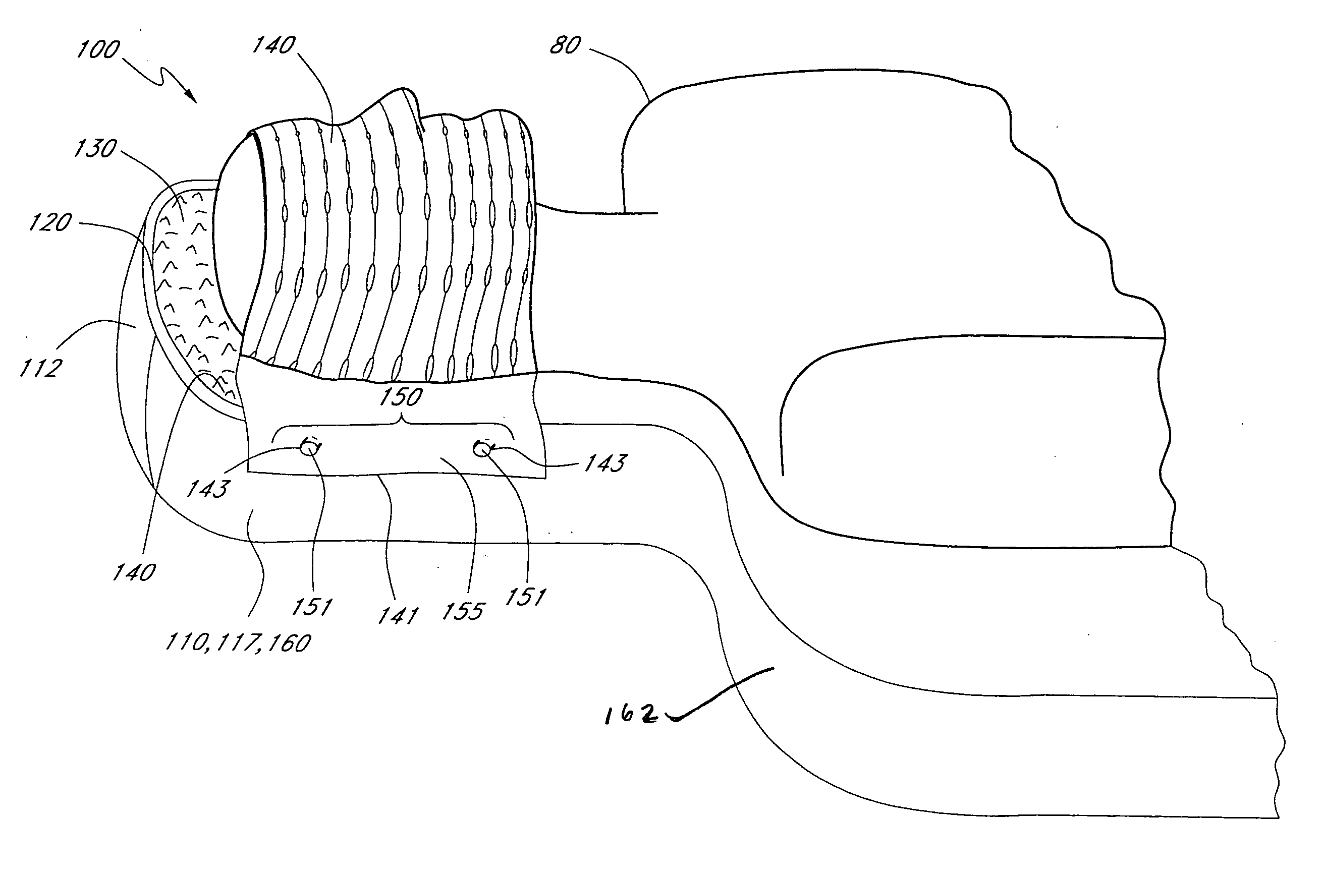
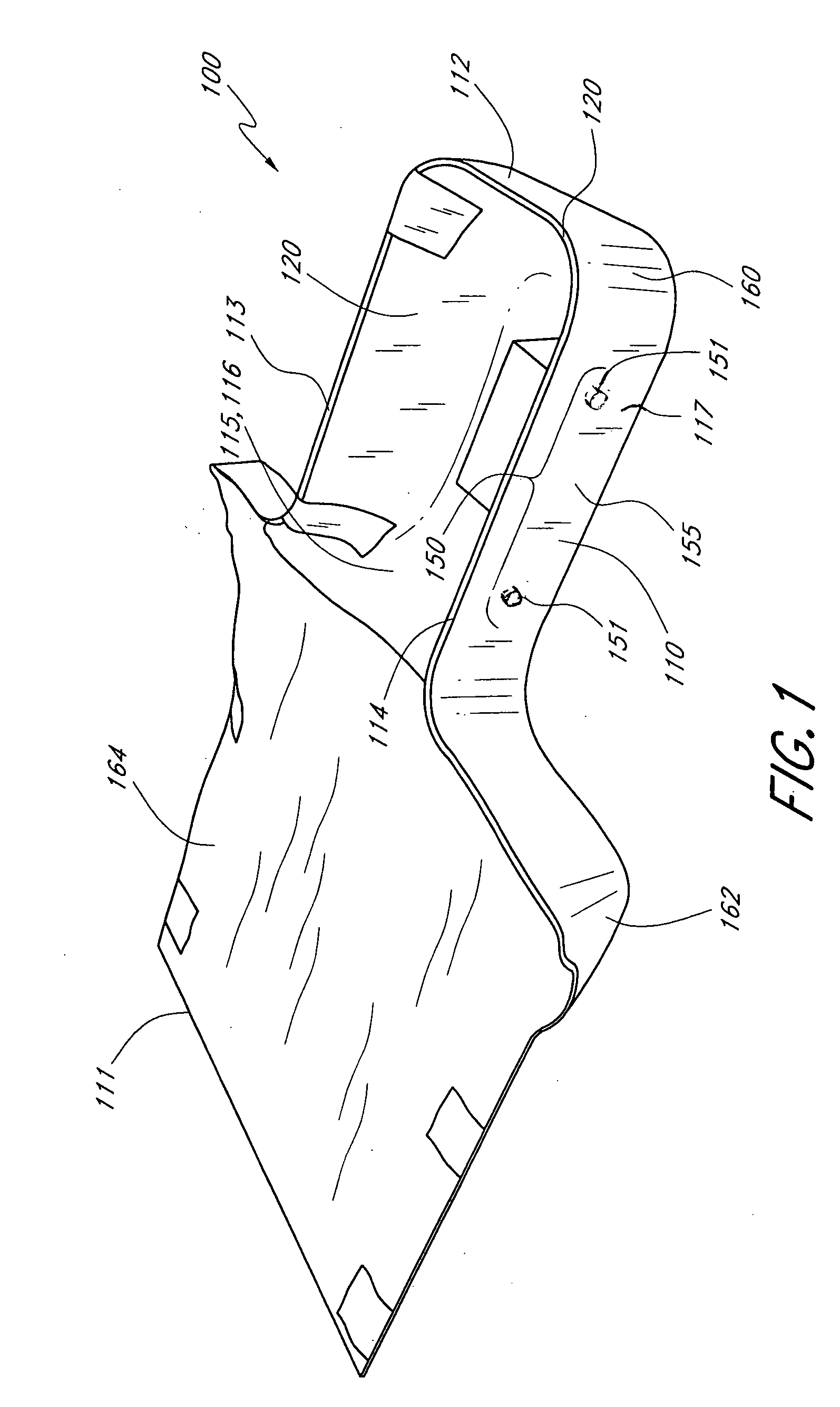
[0022] In accordance with another aspect of the embodiments described herein, the head-and-neck support device is designed to reduce the attenuation or distortion of radiation beams directed at the patient. The materials for the various elements of the head-and-neck support device or pod are chosen to minimally perturb or attenuate the intensity of radiation beams directed at the patient. The chosen materials for the pod preferably make the pod compatible x-rays, magnetic resonance imaging (MRI), positron emission tomography (PET), proton beams, electron beams, etc. For example, suitable materials for the shell include Spectra® (a polyethylene fiber), Kevlar® (an aramid fiber), fiberglass, or the like. The materials for the shell are preferably physically thin, yet strong enough to provide cantilevered support for the head and neck region of the patient. The materials for the shell typically have low atomic numbers (e.g., chains of Hydrogen and Carbon, such as, for example, Spectra® or the like) to minimally perturb radiation beams.
[0037] In accordance with another aspect of the embodiments described herein, the radiation therapy support device can be configured for any anatomical region of the patient. The features of the support device described herein is not necessarily limited for use in the head and neck region. In another embodiment, the support device is dimensioned and configured to provide cantilevered support to the lower and / or middle regions of the patient's anatomy. In still another embodiment, the support device is shaped according to the outline of the patient's whole body and functions as a whole body pod that facilitates the delivery of radiation beams from almost any angle and that reduces the attenuation or perturbation of any radiation beam doses to be delivered to the patient.

Problems solved by technology

Another problem associated with bulky facemask attachment surfaces is that beam delivery devices (e.g., the nozzle of the radiation beam source) are prevented from being placed close to the patient's skin.

Method used


Image

  • Method and device for registration and immobilization
  • Method and device for registration and immobilization
  • Method and device for registration and immobilization

Examples


Embodiment Construction

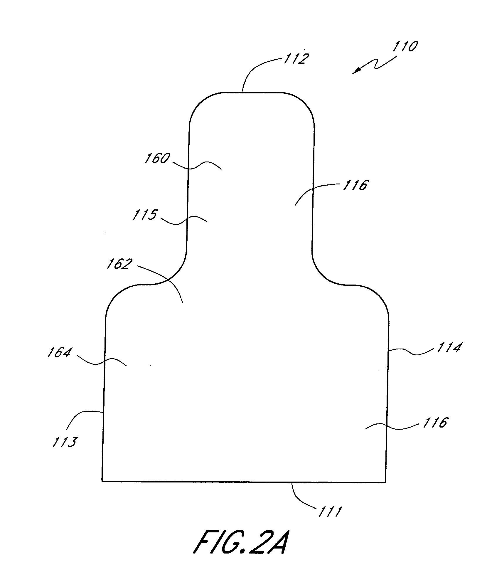
[0044] In accordance with one aspect of the embodiments described herein, there is provided a device that facilitates registration and immobilization of patients undergoing radiation treatment without restriction of directions, thereby allowing optimization of the treatment delivery. More specifically, there is provided a support device for the head and neck region of patients undergoing radiation therapy (e.g., treatment with protons, x-rays, gamma rays, etc.). The head-and-neck support device is typically mounted onto one end of a table or a whole-body support device, which is often attached to a patient positioning system (e.g., a robotic arm or a manually adjustable table or couch). The head-and-neck support device generally comprises a support shell, an immobilization device (e.g., a facemask), and a facemask-to-shell attachment system.

[0045] In one embodiment, illustrated in FIG. 3, the support device comprises a pod 100 for the head and neck region of the patient 80. The pod...


PUM


Abstract

Support devices and pods for the head and neck region of patients undergoing radiation therapy are provided herein. The pod generally includes a support shell shaped to generally conform to the shape of the head and neck region of the patient, a foam insert that conforms to the head and neck region of the patient, and an immobilization facemask attached directly to the shell, thereby facilitating close placement of the radiation beam delivery device to the patient and reducing any attenuation and perturbation of radiation doses directed at the patient. The components of the pod are made from materials having properties that reduce any attenuation and perturbation of prescribed radiation doses.

Description

RELATED APPLICATIONS [0001] This application claims priority to U.S. Provisional Application No. 60 / 583,063, filed Jun. 25, 2004, titled METHOD AND DEVICE FOR REGISTRATION AND IMMOBILIZATION, and to U.S. Provisional Application No. 60 / 614,158, filed Sep. 29, 2004, titled METHOD AND DEVICE FOR REGISTRATION AND IMMOBILIZATION, the contents of each of which are hereby incorporated in their entirety into this disclosure by reference.STATEMENT REGARDING FEDERALLY SPONSORED RESEARCH OR DEVELOPMENT [0002] This invention was made with United States Government support under Cooperative Agreement Number DAMD17-97-2-7016 with the National Medical Technology Testbed, Inc., United States Department of the Army. The United States Government has certain rights in this invention.BACKGROUND OF THE INVENTION [0003] 1. Field of the Invention [0004] The present invention relates to a registration and immobilization device for radiation therapy, and more particularly to a support device that facilitates...

Claims


Application Information

Patent Timeline
IPC IPC(8): A61N5/10G21G4/00H05H1/00
CPCA61B2019/206A61N5/1049A61N2005/1097A61B5/055A61N5/10A61N5/1039A61N2005/1087A61N2005/1089A61B6/037A61B90/18
Inventor MOYERS, MICHAEL F.
Owner LOMA LINDA UNIV MEDICAL CENT
Learn More