Digital frequency-multiplying DLLs

a digital frequency and frequency multiplication technology, applied in the field of digital frequency multiplication delaylocked loops, can solve the problems of insufficient application, limited smallest possible phase increment, and difficult mass production of analog designs within stated specifications, so as to reduce the effect of reducing the overall resolution of the system

Inactive Publication Date: 2005-12-29
MICRON TECH INC
View PDF31 Cites 16 Cited by
  • Summary
  • Abstract
  • Description
  • Claims
  • Application Information

AI Technical Summary

Benefits of technology

[0009] In accordance with the invention, a digital variable delay line replaces the analog delay units of a standard frequency-multiplying delay-locked loop (DLL). To produce a variable frequency ring oscillator, the number of digital delay units used in the ring oscillator is varied. The resolution of a DLL is a measure of the DLL's precision. The phase error of a DLL cannot generally be adjusted below the resolution. A digitally-controlled frequency-multiplying DLL having a variable delay line in accordance with the invention can achieve a resolution of 2*tud for each oscillation of the variable delay line, where tud is the time of one delay unit. An overall resolution of 2*M*tud, where M is the multiplication factor of the DLL, can be achieved.
[0011] Multiple phase mixer stages can be added to provide further fine tuning capabilities. Each subsequent phase mixer stage reduces the overall resolution of the system by a further factor of L. For example, two phase mixer stages each having an L=10 reduces the overall resolution of the system by a factor of 100 (the first phase mixer stage allows the output to be adjusted in 1 / 10 increments of a delay unit, while the second phase mixer stage allows the output to be further adjusted in 1 / 10 increments of the first stage's 1 / 10 increments).

Problems solved by technology

However, it is well known that analog designs are more difficult to mass produce within stated specifications and are less portable to various process technologies than digital designs.
However, the smallest possible phase increment is typically limited to the delay through a single unit delay, which may not suffice for many applications.

Method used


Image

  • Digital frequency-multiplying DLLs
  • Digital frequency-multiplying DLLs
  • Digital frequency-multiplying DLLs

Examples


Embodiment Construction

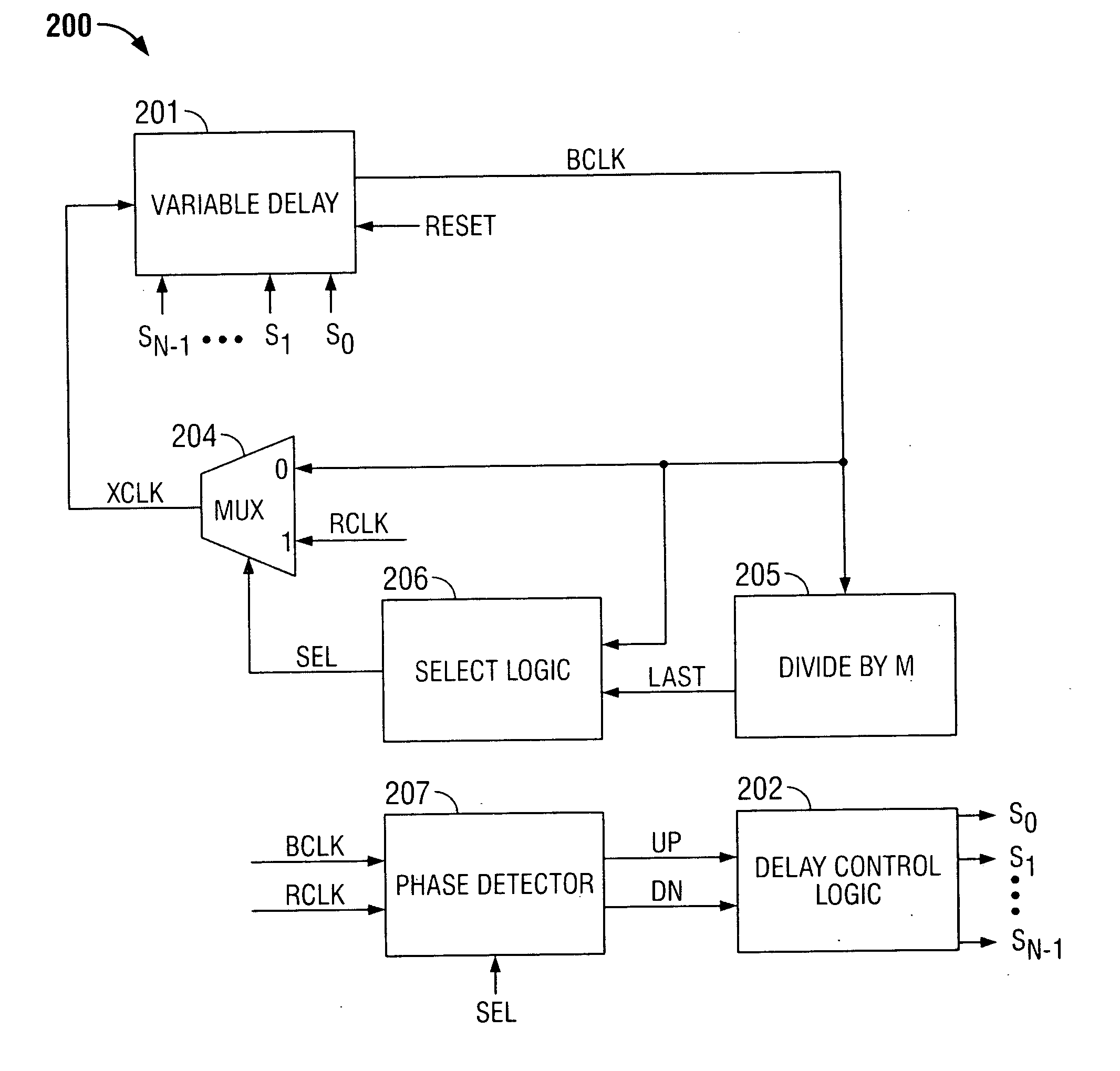
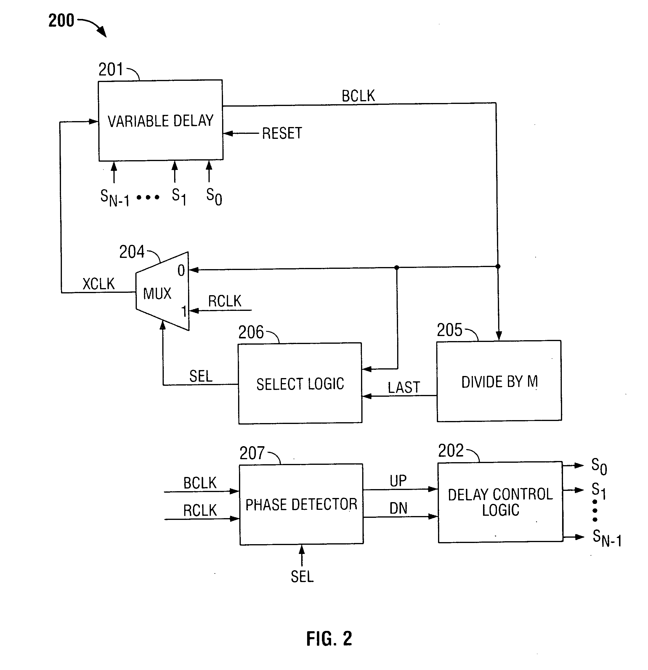
[0024] The invention provides a digitally-controlled frequency-multiplying delay-locked loop (DLL) that provides programmable clock multiplication with little, if any, phase error.

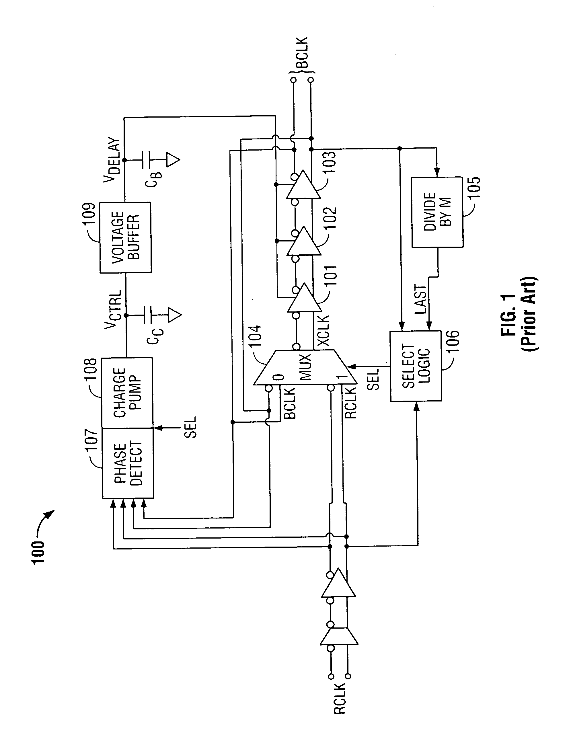
[0025]FIG. 1 shows a typical analog frequency-multiplying DLL 100. (Note that DLL 100 is a differential circuit and that, for clarity, pairs of differential signals will be referred to collectively in singular form. For example, instead of referring to BCLK and BCLK′ (its complement), both will be referred to as BCLK.) Reference clock signal RCLK is input into DLL 100, and high-frequency output signal BCLK is output at a frequency M times the frequency of clock signal RCLK. The phase difference between RCLK and BCLK is ideally zero.

[0026] DLL 100 includes multiplexer 104 and delay elements 101-103 coupled to form a ring oscillator. Reference clock signal RCLK enters analog inverting delay element 101 via multiplexer 104. After the rising edge of signal RCLK is received, multiplexer 104 switches through t...


PUM


Abstract

Digital delay-locked loops (DLLs) and methods are provided for signal frequency multiplication. Analog delay elements of typical frequency-multiplying DLLs are replaced with digital and digitally-controlled elements including a variable delay line. The number of unit delay elements in the delay line can be selected to produce a desired output signal delay. Phase-mixing of multiple variable delay line outputs achieves finer delay-time adjustments.

Description

BACKGROUND OF THE INVENTION [0001] This invention relates to frequency-multiplying delay-locked loops (DLLs). More particularly, this invention relates to digitally-controlled frequency-multiplying DLLs. [0002] Frequency-multiplying DLLs typically generate a high-frequency clock signal based on a lower frequency reference signal. Such DLLs then attempt to maintain a specific phase relationship between the generated clock signal and that reference signal. A ring oscillator is used to generate an output signal approximately M times the frequency of the reference signal, where the value of M is selectable. Every M pulses of the output signal, the phase of the output signal and the reference signal are compared. The delay of the ring oscillator is then adjusted, if necessary, in response to the comparison. This resets the phase of the output signal with respect to the reference signal. Accordingly, any phase deviation that may occur can accumulate for only M cycles at most before being ...

Claims


Application Information

Patent Timeline
Patent Type & Authority Applications(United States)
IPC IPC(8): H03L7/06H03L7/089H03L7/099H03L7/18
CPCH03L7/089H03L7/18H03L7/0998H03L7/0997
Inventor LEE, SEONG-HOON
Owner MICRON TECH INC
Why Eureka
Try Eureka