Eureka AIR delivers breakthrough ideas for toughest innovation challenges, trusted by R&D personnel around the world.

Horizontal augmented thrust system and method for creating augmented thrust

a horizontal thrust and augmentation system technology, applied in the direction of wing shapes, jet flaps, transportation and packaging, etc., can solve the problems of disproportionate lift generated by one of the wings, weight and wing structural load penalties from the ducting or supply line, loss of not, etc., to achieve small service or maintenance, increase the effect of thrust and low cos

Active Publication Date: 2006-01-05
THE BOEING CO
View PDF6 Cites 20 Cited by
  • Summary
  • Abstract
  • Description
  • Claims
  • Application Information

AI Technical Summary

Benefits of technology

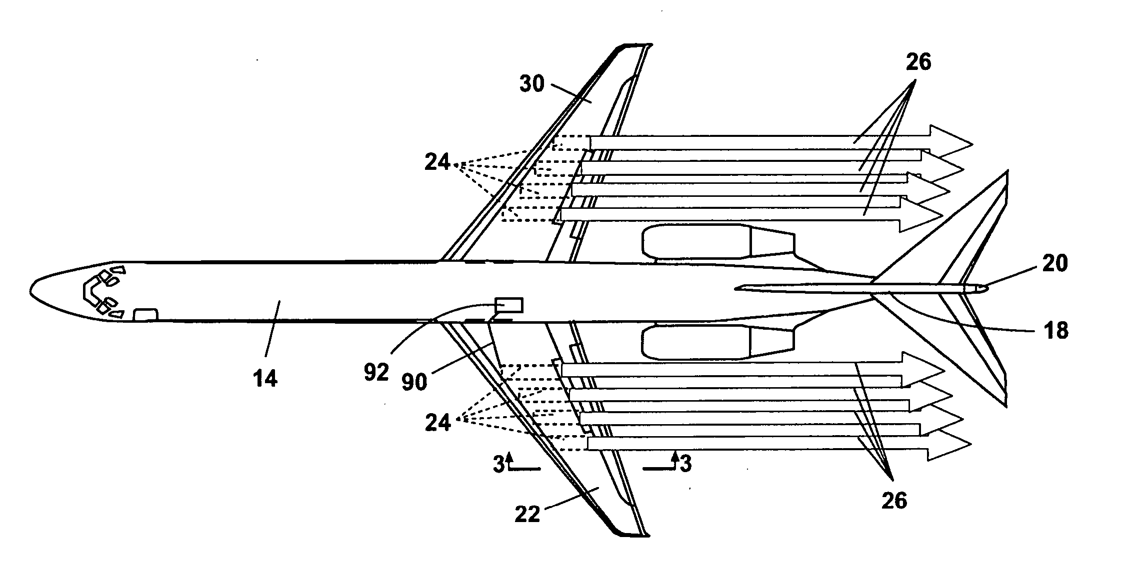
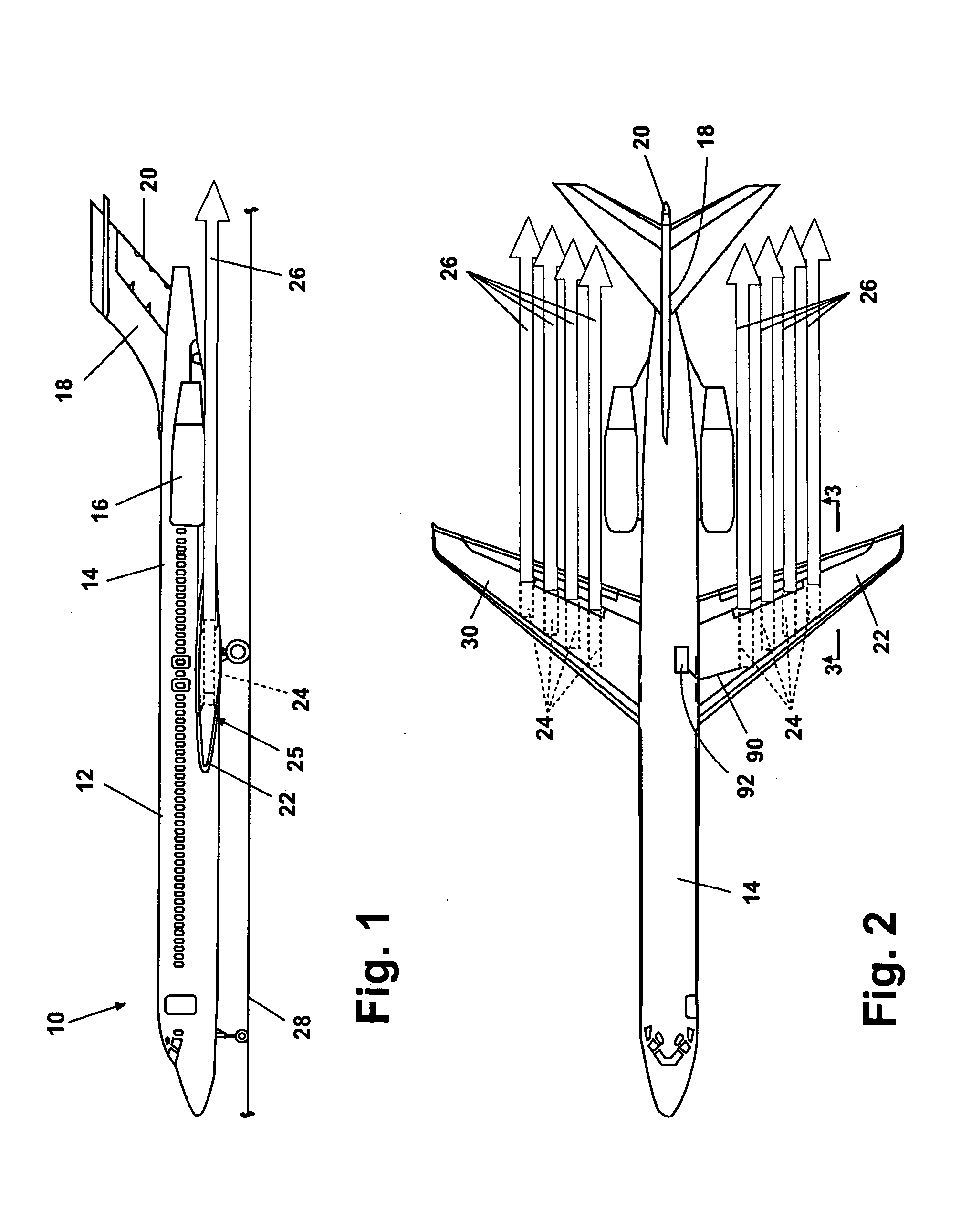
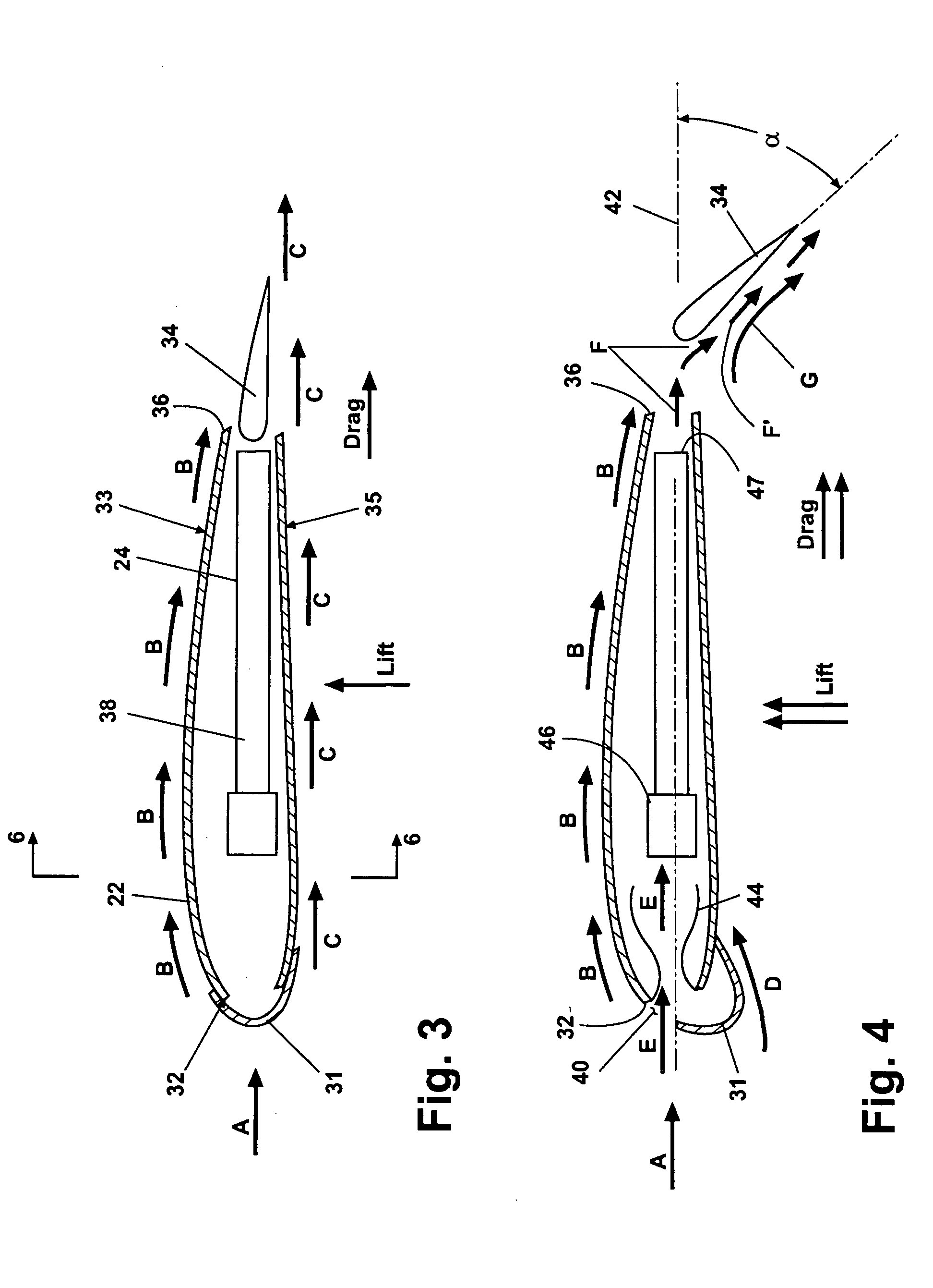
[0009] A horizontal augmented thrust system and method for creating augmented thrust of the present invention offers several advantages. By positioning one or more pulse jets within the boundary of an aircraft wing, the pulsejets can directly provide a horizontal thrust component in addition to the thrust provided by the aircraft's main flight engine(s), thereby increasing thrust during takeoff and landing phases. Pulse jets of the present invention have no moving parts and can therefore be configured within the wings as integral load bearing structural wing members. This design requires only a fuel injector and an ignition source and is therefore very simple, low cost and needs little service or maintenance. The pulsed discharge of the pulse jet engines when directed over a wing flap increases air speed over the flap, therefore increasing wing lift. The pulsed discharge also delays buildup of boundary layer air on the flaps, therefore permitting an increased deployment angle of the flap(s) before airstream separation occurs. This in turn provides more lift for lower speeds with commensurate reductions in takeoff / landing distances.

Problems solved by technology

Disadvantages of these systems include the weight and wing structural load penalties from the ducting or supply lines.
Also, failure of a propulsion engine, for example during takeoff, can result in loss of not only propulsion from the main engine, but loss of the additional thrust to a specific wing or set of flaps, which can cause a disproportionate lift generated by one of the wings and further exacerbates the loss of engine thrust.
Plumbing for large amounts of relatively high pressure / temperature gas requires increased duct weight (to resist pressure) and increased diameter (which results in increased weight plus loss of aircraft volume) to accommodate insulation which prevents heat from soaking into the vehicle.
Ducting also is often required to run the length of the wing(s) to reach each flap, which not only incurs large pressure losses but also reduces the resulting fuel holding capability of the wing(s).
Each of the ducts or dedicated lines also requires individual controls to open or shut the duct or line, which further adds complexity and cost.
These systems have limited ability to throttle the augmented flow to the flaps, resulting in the inability to vary the wing lift during aircraft acceleration for takeoff or prior to landing.
An un-choked system allows backflow and subsequent non-uniform flow which in turn can cause asymmetric lift.
For example, during preparation for landing the main flight engines are throttled back at the same time when the flaps are extended to increase wing lift, therefore airflow over the flaps from the augmentation system is not optimized when it is most needed.

Method used


Image

  • Horizontal augmented thrust system and method for creating augmented thrust
  • Horizontal augmented thrust system and method for creating augmented thrust
  • Horizontal augmented thrust system and method for creating augmented thrust

Examples


Embodiment Construction

[0024] The following description of the preferred embodiments is merely exemplary in nature and is in no way intended to limit the invention, its application, or uses.

[0025] Referring generally to FIG. 1 and according to a preferred embodiment of the present invention, a horizontal augmented thrust system and method for creating augmented thrust of the present invention includes an augmented thrust system 10. An aircraft 12 including a fuselage 14, at least one flight propulsion engine 16, a tail 18, a rudder 20 and a port wing 22. Port wing 22 includes at least one pulse jet engine 24 completely enclosed within an outer envelope 25 of port wing 22. Each pulse jet engine 24 produces a horizontal augmented thrust 26. Aircraft 12 is normally propelled in a horizontal direction of flight by flight propulsion engines 16. In an exemplary use of augmented thrust system 10, aircraft 12 accelerates along a ground surface 28 such as a runway. Each of pulse jet engines 24 are ignited to prod...


PUM


Abstract

A horizontal augmented thrust system includes at least one wing. The wing includes a wing outer envelope, a trailing edge and a flap. At least one pulse jet engine is positioned entirely within the wing outer envelope. The pulse jet engine produces a pulsating thrust dischargeable adjacent the trailing edge of the wing and onto the flap.

Description

FIELD OF THE INVENTION [0001] The present invention relates in general to aircraft thrust systems and more specifically to a wing adapted thrust augmentation system and a method for creating an aircraft augmented thrust. BACKGROUND OF THE INVENTION [0002] Aircraft thrust augmentation systems are known which duct portions of flight engine thrust into the wings of the aircraft for discharge onto or adjacent to the wing flaps. These augmentation systems provide a steady state flow of engine exhaust during at least portions of the aircraft's flight, takeoff or landing phases to increase airflow over the flaps and thereby increase wing lift during periods when the aircraft's speed is below or approaching wing stall speed. Many of these systems use diverted axial engine fan or nozzle flow through dedicated ducting constructed in the main flight wings of the aircraft. Some of these systems provide individual thrust supply lines to each flap. [0003] Disadvantages of these systems include th...

Claims


Application Information

Patent Timeline
IPC IPC(8): B64C3/00
CPCB64C9/38Y02T50/32B64D27/18Y02T50/30
Inventor OUELLETTE, RICHARD P.KUTZMANN, AARON J.CUMMINGS, DAROLD B.
Owner THE BOEING CO
Why Eureka
Eureka Blog
Learn More