Power amplifier protection circuit and associated methods

a protection circuit and power amplifier technology, applied in the direction of transmission monitoring, baseband system details, modulation, etc., can solve the problems of power amplifiers being susceptible to damage, node voltages could exceed the cmos breakdown voltage, and permanent damage to power amplifiers, so as to reduce the temperature of power amplifiers

Active Publication Date: 2006-01-05
QUALCOMM INC
View PDF19 Cites 10 Cited by
  • Summary
  • Abstract
  • Description
  • Claims
  • Application Information

AI Technical Summary

Benefits of technology

[0006] A power amplifier according to one illustrative embodiment of the invention uses one or more techniques for protecting the power amplifier from damage from high temperatures. In one embodiment, a control circuit changes the operation of the power amplifier depending on one or more temperature thresholds being reached. In one example, the control circuit shuts down the power amplifier in response to the sensed temperature. In another example, the control circuit attempts to reduce the temperature of the power amplifier without shutting down the power amplifier. These two examples can be operated within the same design.

Problems solved by technology

Power amplifiers are susceptible to damage when subjected to extreme conditions such as high temperatures.
High temperatures can have various causes, including extreme current due to mismatched loads at the antenna, high duty cycle from data transmission, battery regulation when recharging a battery, or high ambient temperatures.
At the extremes of these mismatched conditions, a power amplifier, regardless of which process technology has been implemented, could experience stresses that have the potential to cause permanent damage to the power amplifier.
In a power amplifier implemented using a complementary metal oxide semiconductor (CMOS), when the load impedance at the antenna is high (e.g., 500 ohms), the node voltages could exceed the CMOS breakdown voltage and cause permanent damage.
When the load impedance of a load is low (e.g., 5 ohms), the current supplied to the load may be high enough to result in thermal problems.
One problem with this approach is that using only current sensing may inhibit certain modes of operation which are acceptable, such as a high current for a short period of time.
Also, some current sensing techniques do not take into account environmental conditions such as ambient temperature, ventilation, heat sinking, etc.
Another problem with this approach relates to the fact that the system only knows the current drawn, which can result in flaws.
For example, such a system can not take into account the efficiency of the power amplifier or the true junction temperature of the die.
Such a system is also inefficient, since the resistor will dissipate power, thus reducing overall efficiency.

Method used


Image

  • Power amplifier protection circuit and associated methods
  • Power amplifier protection circuit and associated methods
  • Power amplifier protection circuit and associated methods

Examples


Embodiment Construction

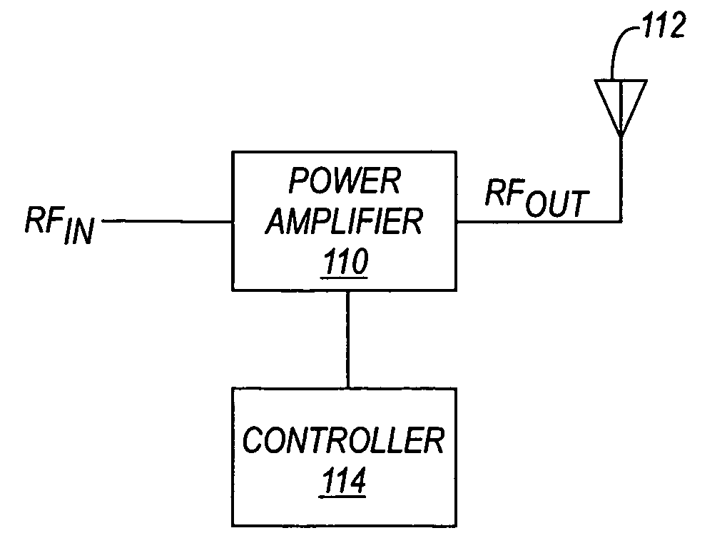
[0015] In order to provide a context for understanding this description, the following description illustrates one example of a typical application of the present invention. A power amplifier of the present invention may be used for any desired applications, including wireless transmission systems such as mobile or cellular communication devices or other wireless devices. In a wireless device, the wireless device may include a transceiver, an antenna module, and an antenna. Coupled between the transceiver and the antenna module is an RF power amplifier for amplifying signals for transmission via the antenna. In the case of a wireless mobile application, the invention may be applied to GSM, CDMA, PCS, DCS, etc., or any other wireless systems. This is just one example of an application of a power amplifier utilizing the present invention. The invention may also be used in any other application requiring a power amplifier.

[0016] Generally, the present invention provides techniques for...


PUM


Abstract

In a power amplifier, techniques are provided for protecting the power amplifier from temperature extremes resulting from conditions such as load mismatches. After sensing the temperature of the power amplifier, the operation of the RF power amplifier is controlled accordingly. In one example, the power amplifier is shut down when the sensed temperature reaches a threshold value, which can be set to a value just below the point where permanent damage would occur. In another example, when a threshold temperature is reached, the operation of the power amplifier is changed, to prevent the temperature of the power amplifier from rising to a level that would damage the power amplifier.

Description

FIELD OF THE INVENTION [0001] This invention relates to the field of power amplifiers. In particular, this invention is drawn to techniques for protecting power amplifiers from damage, such as damage from high temperatures. BACKGROUND OF THE INVENTION [0002] Power amplifiers are susceptible to damage when subjected to extreme conditions such as high temperatures. High temperatures can have various causes, including extreme current due to mismatched loads at the antenna, high duty cycle from data transmission, battery regulation when recharging a battery, or high ambient temperatures. [0003] A typical RF power amplifier can be specified to handle load mismatches on the order of a 10:1 ratio. A mismatch of 10:1 implies that a power amplifier must drive loads of 5 ohms to 500 ohms. Nominally, the RF amplifier is specified is specified to drive a 50 ohm load. At the extremes of these mismatched conditions, a power amplifier, regardless of which process technology has been implemented, c...

Claims


Application Information

Patent Timeline
Patent Type & Authority Applications(United States)
IPC IPC(8): H03C1/62H01Q11/12H04B1/04
CPCH03F1/52H04B1/036H03F2200/468
Inventor OUZILLOU, MENDY M.BOCOCK, RYAN M.
Owner QUALCOMM INC
Why Eureka
Try Eureka