
Biological signal sensor on a body surface

a biomedical sensor and body surface technology, applied in the field of biomedical sensors, can solve the problems of patient skin irritation and/or skin infection, inability to use for a longer time, and other problems commonly encountered in long-term ecg monitoring

Inactive Publication Date: 2006-01-05
LOBODZINSKI S SUAVE
View PDF11 Cites 26 Cited by
  • Summary
  • Abstract
  • Description
  • Claims
  • Application Information

AI Technical Summary

Benefits of technology

[0009] Embodiments of the present invention address the needs of the long-term, in-hospital and emergency response monitoring markets by providing an inexpensive, one-time use integrated electrode-leadwire-patient cable system that can be either used as a separate device or integrated into a garment for long term ECG monitoring applications.

Problems solved by technology

Longer-term applications require extensive taping of the electrodes and the connected patient cable to the body, thus making it impractical for longer-term use.
Typically, the leadwires and patient cables are not sterilized and have been shown to be a source of cross infections in the hospital setting.
Other problems are also commonly encountered in long-term ECG monitoring.
Long-term contact of gel sealed under the urethane foam electrode cap causes patient skin irritation and / or skin infection.
Half-cell potential variations at the skin-electrode interface due to mechanical deformations of the skin surface under the electrodes cause excessive artifacts in the monitored results.
Patient movement that pull on the lead electrode wires cause motion artifacts in the monitored results.
Excessive patient perspiration under the electrode cap (gel leakage, baseline wonder etc.) also cause artifacts in the monitored results.
In addition, current techniques do not provide patient convenience, such as resistance to water (showers or bath) and mechanical exposure (wearing normal clothing and conducting normal daily activities).

Method used


Image

  • Biological signal sensor on a body surface
  • Biological signal sensor on a body surface
  • Biological signal sensor on a body surface

Examples


Embodiment Construction

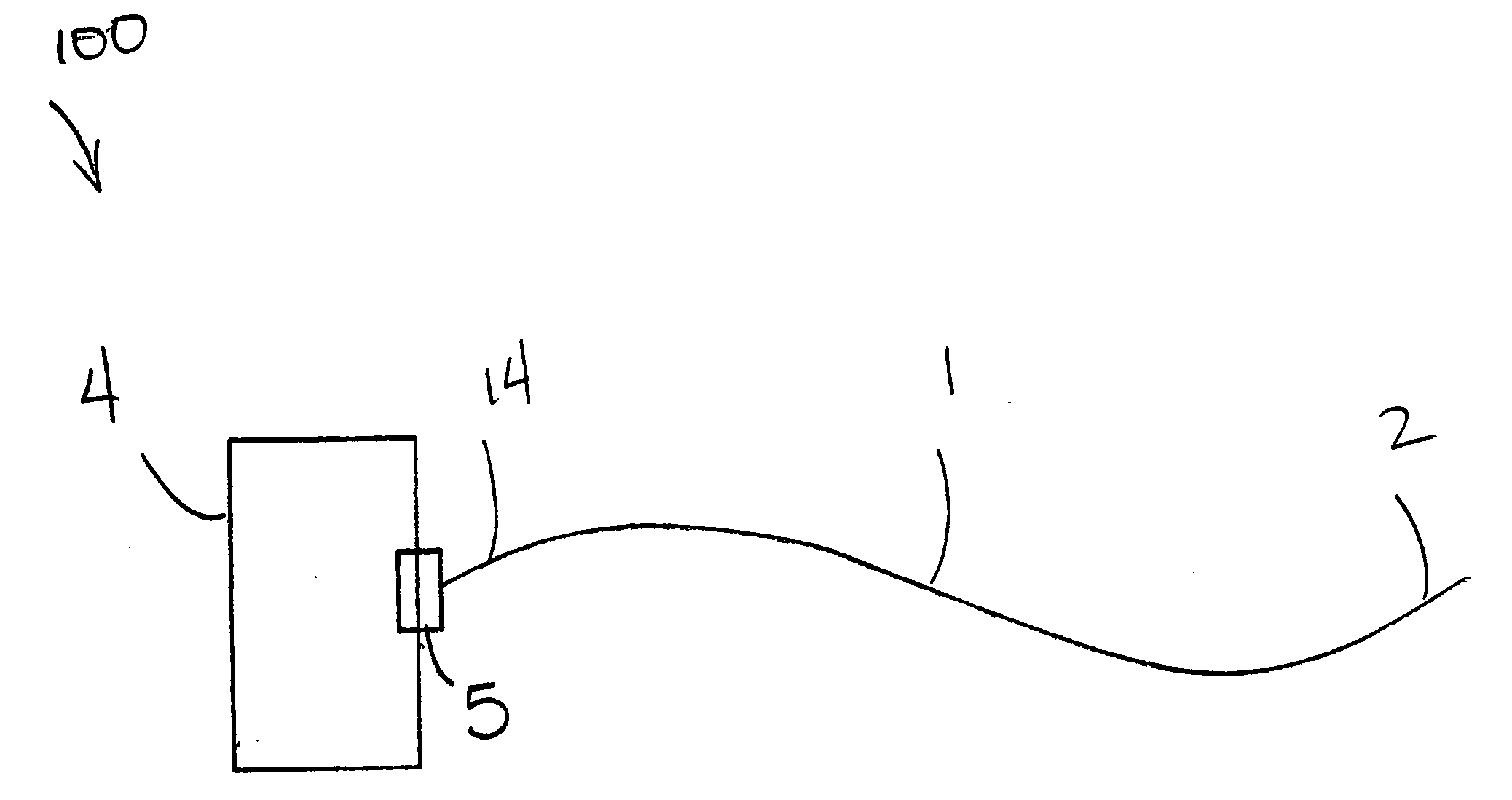
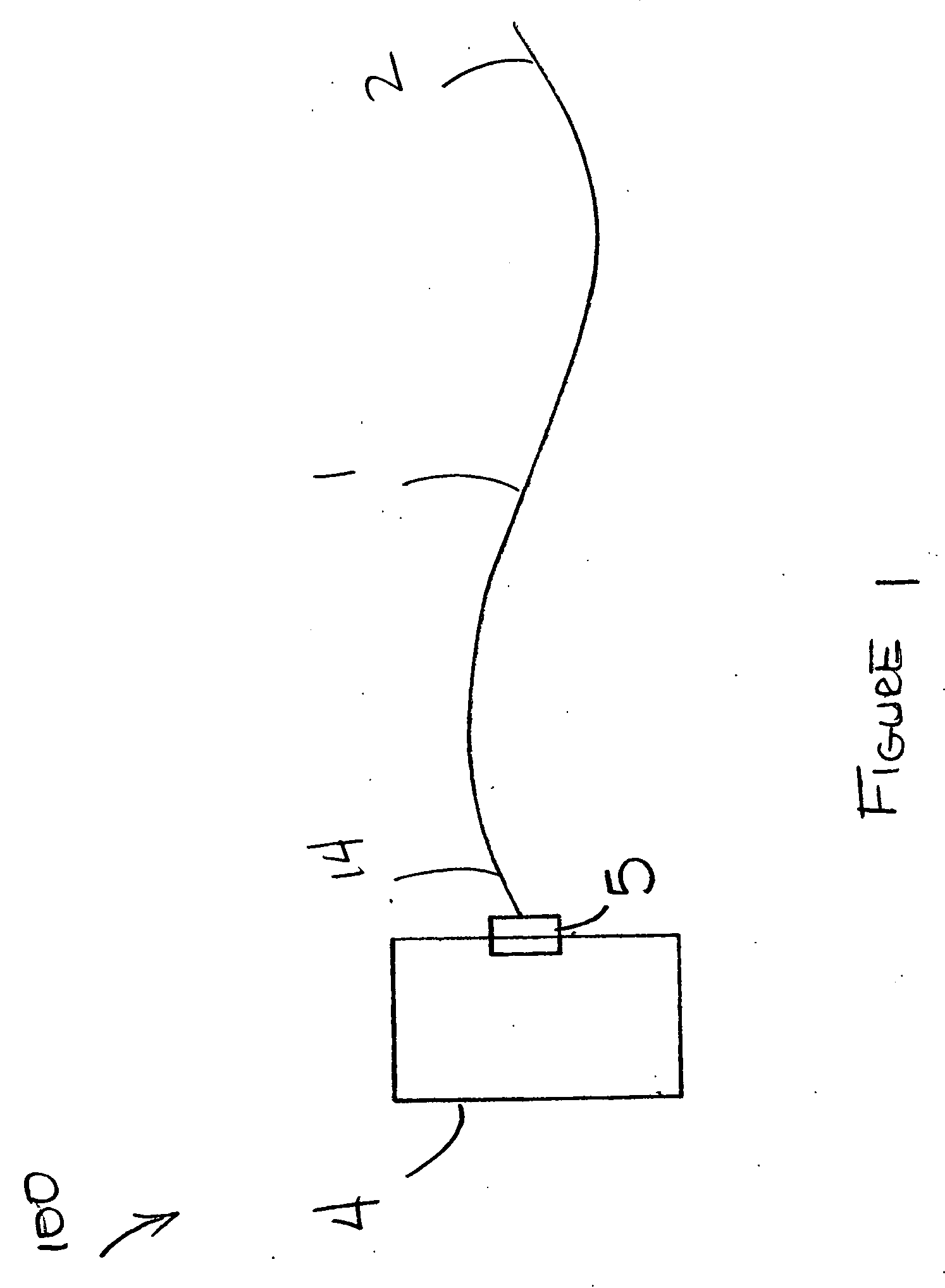
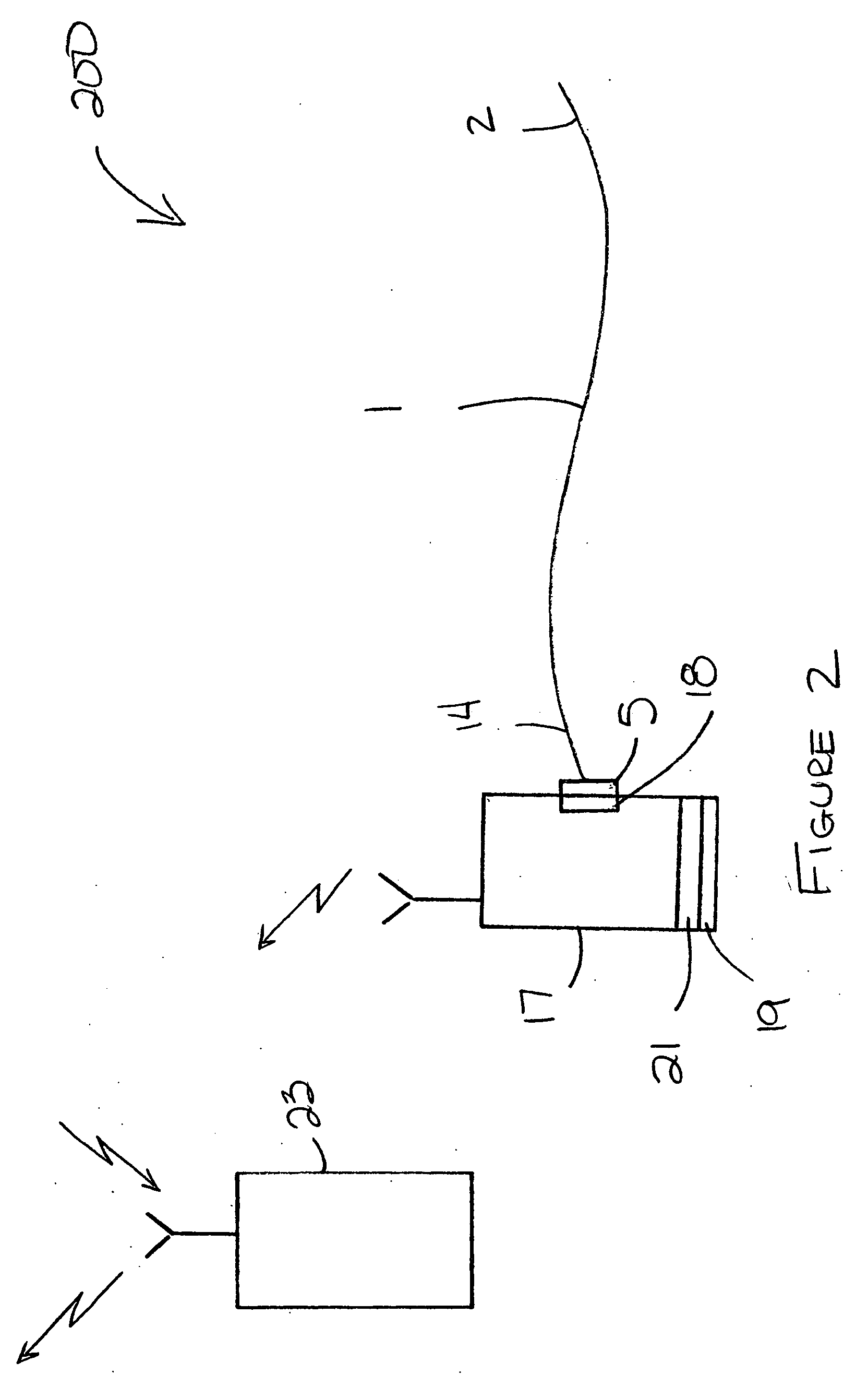
[0033]FIG. 1 schematically illustrates an embodiment of a biological signal sensor or biomedical sensor 100. The biomedical sensor 100 comprises a strand of an electrically conductive fiber 1, an ECG amplifier or electrocardiograph 4, and a sensor connector 5 electrically connecting the fiber 1 to the electrocardiograph 4. The biomedical sensor 100 acquires biological signals through contact with a subject and conducts the biological signals to the electrocardiograph 4.

[0034] The strand of the electrically conductive fiber 1 forms a sensor tip 2 and a non-sensing end 14. The fiber 1 can be a metal-coated synthetic fiber such as, for example, acrylic, nylon, and the like.

[0035] In an embodiment, the sensor connector 5 comprises a nylon frame that encapsulates the non-sensing end of the fiber 14, and protruding domes that squeeze the fiber 14 to a contact thus forming an electrical connection between the fiber and the contact. In an embodiment, the connector comprises a plurality of...


PUM


Abstract

An electrically conductive fiber and a coupled biomedical sensor are described. An electrically conductive core of the fiber includes a multiplicity of synthetic conductive filaments and an outer nonconductive fiber layer. The sensor area of the electrically conductive fiber is coated by thin film of silver ink and thin film of silver-silver chloride ink. The electrically conductive fiber's porous surface contacts the thin silver ink coating and the silver coating contacts the silver-chloride ink coating. A surface of the biomedical sensor is coated by a thick film of ionically conductive media, containing an electrolyte, in contact with the silver-chloride coating. The electrolyte diffuses into a porous structure of electrically conductive yarn.

Description

[0001] The present application claims priority benefit under 35 U.S.C. § 119(e) from U.S. Provisional Application No. 60 / ______, filed May 24, 2004, by S. Suave Lobodzinski, titled “A Method and a System for Sensing Biological Signals on the Body Surface,” which is hereby incorporated herein in its entirety by reference.BACKGROUND OF THE INVENTION [0002] 1. Field of the Invention [0003] This invention relates generally to biomedical sensors, and more particularly, to systems and methods for electrically conductive fibers for biomedical sensors. [0004] 2. Description of the Related Art [0005] The practice of medicine utilizes a variety of sensors to measure and record biological signals on the body surface. These include: electrocardiogram, psycho-galvanic reflex of the skin, lactic acid, oxygen concentration, bio-impedance etc. In the electrocardiography applications, the present day ECG recording techniques utilize either non-polarizing Ag / AgCl or polarizing metal electrodes. The e...

Claims


Application Information

Patent Timeline
IPC IPC(8): A61B5/04
CPCA61B5/0408A61B2562/0215A61B5/25A61B5/265A61B5/256A61B5/28A61B5/266
Inventor LOBODZINSKI, S. SUAVE
Owner LOBODZINSKI S SUAVE
Learn More