Microwave plasma nozzle with enhanced plume stability and heating efficiency

a plasma nozzle and microwave technology, applied in plasma welding apparatus, plasma technique, plasma tools, etc., can solve the problems of one or more plasma species temperatures, high operation cost, thermal sensitivity and destruction, etc., to achieve low per unit cost, reduce power consumption, and reduce operational costs

Active Publication Date: 2006-01-12
NOXILIZER
View PDF43 Cites 44 Cited by
  • Summary
  • Abstract
  • Description
  • Claims
  • Application Information

AI Technical Summary

Benefits of technology

[0013] The present invention provides various systems and methods for generating a relatively cool microwave plasma using atmospheric pressure. These systems have a low per unit cost and operate at atmospheric pressure with lower operational costs, l

Problems solved by technology

A low plasma pressure, on the other hand, may yield one or more temperatures for the plasma species due to insufficient collisions between the species of the plasma.
These technologies have a number of problems that must be dealt with and overcome and these include issues as thermal sensitivity and destruction by heat, the formation of toxic byproducts, the high cost of operation, and the inefficiencies in the overall cycle duration.
Consequently, healthcare agencies and industries have long needed a sterilizing technique that could function near room temperature and with much shorter times without inducing structural damage to a wide range of medical materials including various heat sensitive electronic components and equipment.
These changes to new medical materials and devices have made sterilization very challenging using traditional sterilization methods.
However, due to the complexity and the high operational costs of the batch process units needed for this process, hospitals use of this technique has been limited to ve

Method used


Image

  • Microwave plasma nozzle with enhanced plume stability and heating efficiency
  • Microwave plasma nozzle with enhanced plume stability and heating efficiency
  • Microwave plasma nozzle with enhanced plume stability and heating efficiency

Examples


Embodiment Construction

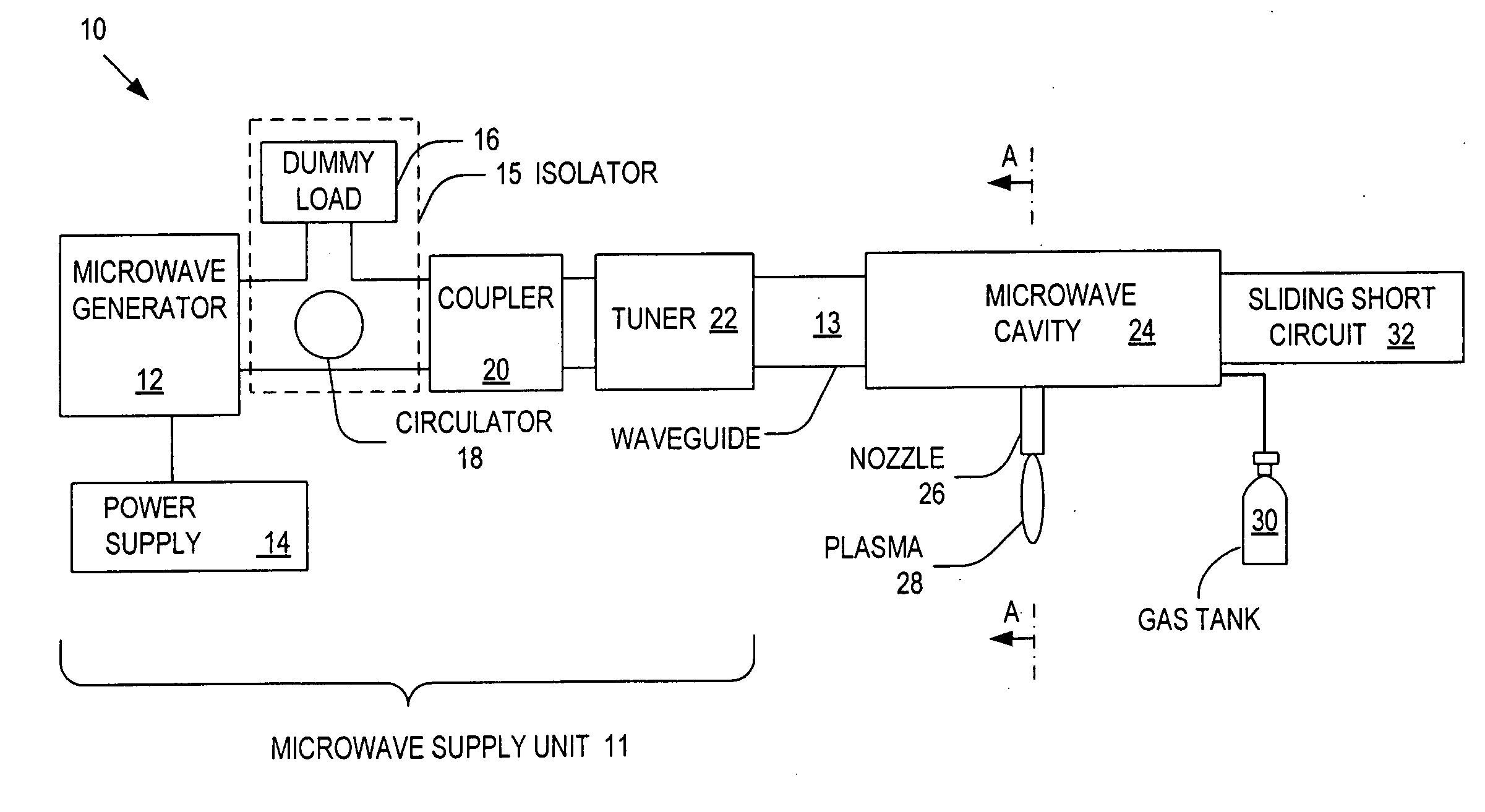
[0029]FIG. 1 is a schematic diagram of a system 10 for generating microwave plasma in accordance with one embodiment of the present invention. As illustrated, the system 10 may include: a microwave cavity 24; a microwave supply unit 11 for providing microwaves to the microwave cavity 24; a waveguide 13 for transmitting microwaves from the microwave supply unit 11 to the microwave cavity 24; and a nozzle 26 connected to the microwave cavity 24 for receiving microwaves from the microwave cavity 24 and generating an atmospheric plasma 28 using a gas and / or gas mixture received from a gas tank 30. A commercially available sliding short circuit 32 can be attached to the microwave cavity 24 to control the microwave energy distribution within the microwave cavity 24 by adjusting the microwave phase.

[0030] The microwave supply unit 11 provides microwaves to the microwave cavity 24 and may include: a microwave generator 12 for generating microwaves; a power supply for supplying power to the...


PUM

PropertyMeasurementUnit
Dielectric polarization enthalpyaaaaaaaaaa
Poweraaaaaaaaaa
Flow rateaaaaaaaaaa

Abstract

Systems and methods for generating relatively cool microwave plasma are disclosed. The present invention provides a microwave plasma nozzle that includes a gas flow tube through which a gas flows, and a rod-shaped conductor that is disposed in the gas flow tube and has a tapered tip near the outlet of the gas flow tube. A portion of the rod-shaped conductor extends into a microwave cavity to receive microwaves passing in the cavity. These received microwaves are focused at the tapered tip to heat the gas into plasma. The microwave plasma nozzle also includes a vortex guide between the rod-shaped conductor and the gas flow tube imparting a helical shaped flow direction around the rod-shaped conductor to the gas flowing through the tube. The microwave plasma nozzle further includes a mechanism for electronically exciting the gas and a shielding mechanism for reducing a microwave power loss through the gas flow tube.

Description

BACKGROUND OF THE INVENTION [0001] 1. Field of the Invention [0002] The present invention relates to plasma generators, and more particularly to devices having a nozzle that discharges a plasma plume which can be generated using microwaves. [0003] 2. Discussion of the Related Art [0004] In recent years, the progress on producing plasma has been increasing. Typically, plasma consists of positive charged ions, neutral species and electrons. In general, plasmas may be subdivided into two categories: thermal equilibrium and thermal non-equilibrium plasmas. Thermal equilibrium implies that the temperature of all species including positive charged ions, neutral species, and electrons, is the same. [0005] Plasmas may also be classified into local thermal equilibrium (LTE) and non-LTE plasmas, where this subdivision is typically related to the pressure of the plasmas. The term “local thermal equilibrium (LTE)” refers to a thermodynamic state where the temperatures of all of the plasma speci...

Claims


Application Information

Patent Timeline
IPC IPC(8): B23K10/00
CPCH05H1/46H05H1/24H05H1/463H05H1/4622
Inventor LEE, SANG HUNKIM, JAY JOONGSOO
Owner NOXILIZER
Why Eureka
Try Eureka