Crystal oscillator nanochannel sensor

Inactive Publication Date: 2006-01-12
TOKYO UNIVERSITY OF PHARMACY AND LIFE SCIENCES
View PDF0 Cites 3 Cited by
  • Summary
  • Abstract
  • Description
  • Claims
  • Application Information

AI Technical Summary

Benefits of technology

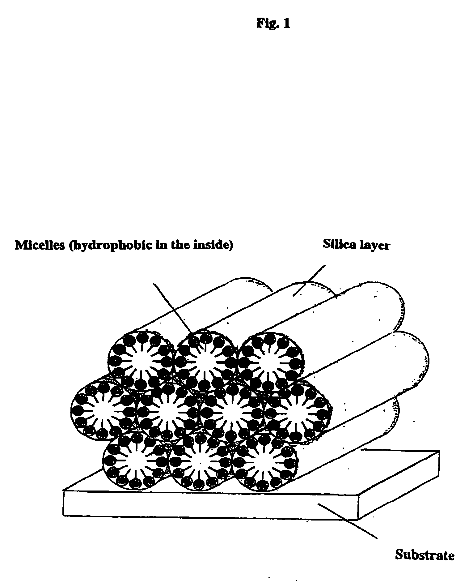
[0015]FIG. 1 is a view typically showing a nanochannel body thin film.
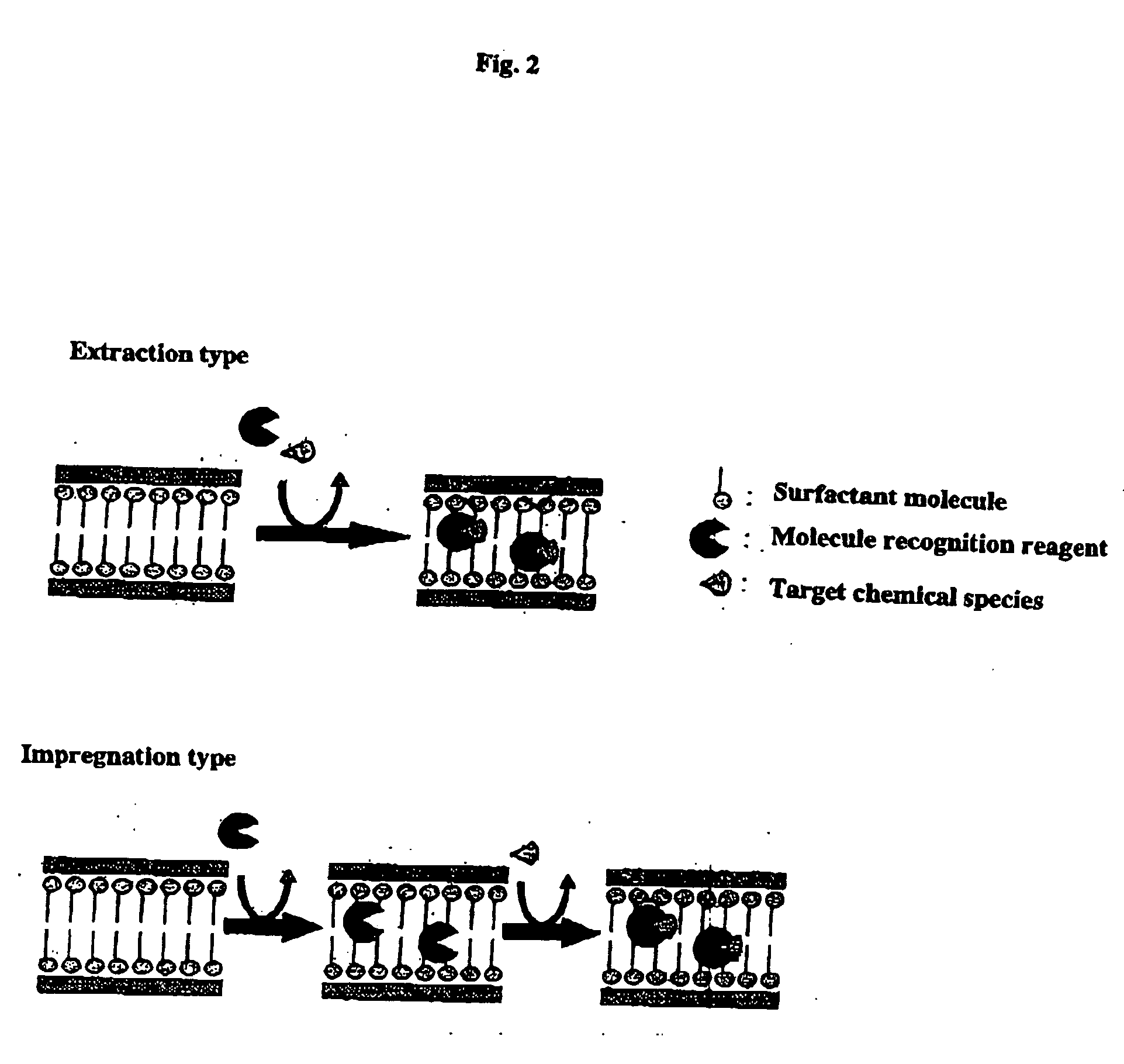
[0016]FIG. 2 is a view typically showing an extraction type and an impregnation type sensor.
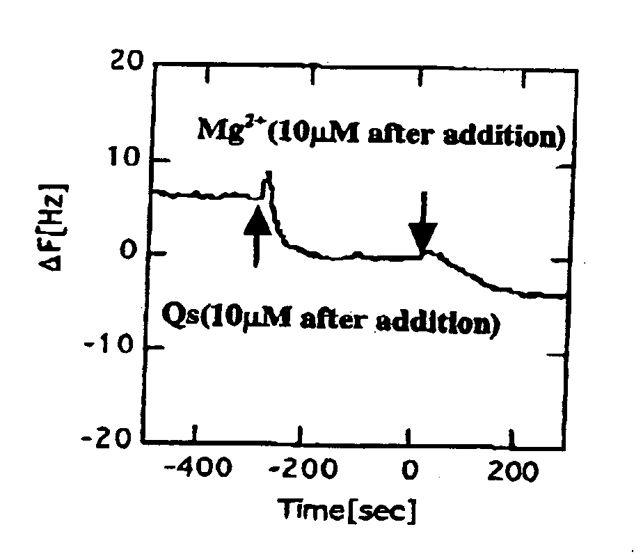
[0017]FIG. 3 is a view illustrating the situation where Mg ions are detected using a crystal oscillator nanochannel sensor in an example.

Problems solved by technology

However, the fact is that almost no technological development of a material with nanometer size pores and its thin film have been made in spite of the above investigations though there is a suggestion as to, for example, utilization as pH sensors or the like.

Method used


Image

  • Crystal oscillator nanochannel sensor
  • Crystal oscillator nanochannel sensor
  • Crystal oscillator nanochannel sensor

Examples


examples

1. Method of Producing a Thin Film

[0049] First, a nanochannel body thin film was formed on the surface of a gold electrode above a crystal oscillator according to the following procedures.

Example of Preparation of a Thin Film-Forming Solution

The thin film solution was made to have the following composition (molar ratio).

TEOS:EtOH:H2O:HCl:CTAB:MPS=1:17.54:5.04:0.004:0.075:0.1

MPS: 3-Mercaptopropyltrimethoxysilane

CTAB: Cetyltrimethylammonium bromide

TEOS: Tetraethyl orthosilicate

[0050] In this composition, MPS is added thereby to improve the adhesion of the thin film to the gold electrode on the crystal oscillator. A thiol group in MPS is considered to be bonded with the surface of gold chemically.

[0051] The procedures are as follows.

(1) EtOH 9.7 mL, TEOS 12.3 mL and 2.78×10⁻³ M HCl 1 mL were mixed and the mixture was refluxed at 60° C. for 90 minutes.

(2) EtOH 18.4 mL, CTAB 1.519 g and 5.48×10⁻² M HCl 14 mL were added to the solution after the solution was refluxed, f...


PUM


Abstract

The crystal oscillator nanochannel sensor comprises a nanochannel structure thin film arranged on an electrode surface of a crystal oscillator and having an oxide layer which contains a surfactant micelle. The sensor senses the existence of a target substance in an analyte solution through a weight change in a nanochannel caused by a recognition reagent and the target substance collected by the recognition reagent. The invention provides a new application of crystal oscillator sensors by utilizing a hydrophobic site provided by the surfactant in a nanometer-size pore.

Description

TECHNICAL FIELD [0001] This invention relates to a crystal oscillator nanochannel sensor. This invention relates, particularly, to a new crystal oscillator nanochannel sensor which is useful as sensors for biochemical analysis, microanalysis and the like in a wide field such as a medical field, sanitary field, industrial field, agricultural field and environmental evaluation field by utilizing a nanometer size porous (nanochannel) structure. BACKGROUND ART [0002] Focusing an attention on nanometer size pores to make studies to produce porous (meso-porous) materials. In these conventional studies, an alkoxy silane compound is hydrolyzed in the presence of a surfactant to thereby form a porous material using the surfactant as a mold. As conventional technologies, there are some reports concerning, for example, the production of a meso-porous material on a mica substrate (Document 1), the production of a meso-porous thin film utilizing the vaporization of a solvent (Document 2) and pat...

Claims


Application Information

Patent Timeline
IPC IPC(8): G01V3/08G01V3/10G01N5/02G01N27/00G01N29/02G01N29/22G01N29/36
CPCB82Y15/00G01N5/02G01N29/022G01N2291/0426G01N29/36G01N2291/0256G01N29/222
Inventor UCHIDA, TATSUYAFUJIWARA, KITAOIKEDA, MIWAKO
Owner TOKYO UNIVERSITY OF PHARMACY AND LIFE SCIENCES
Why Eureka
Try Eureka