Imaging system for emulation of a high aperture scanning system

US20060007541A1Active Publication Date: 2006-01-12CARL ZEISS SMT GMBH

Image

  • Imaging system for emulation of a high aperture scanning system
  • Imaging system for emulation of a high aperture scanning system
  • Imaging system for emulation of a high aperture scanning system

Examples


Embodiment Construction

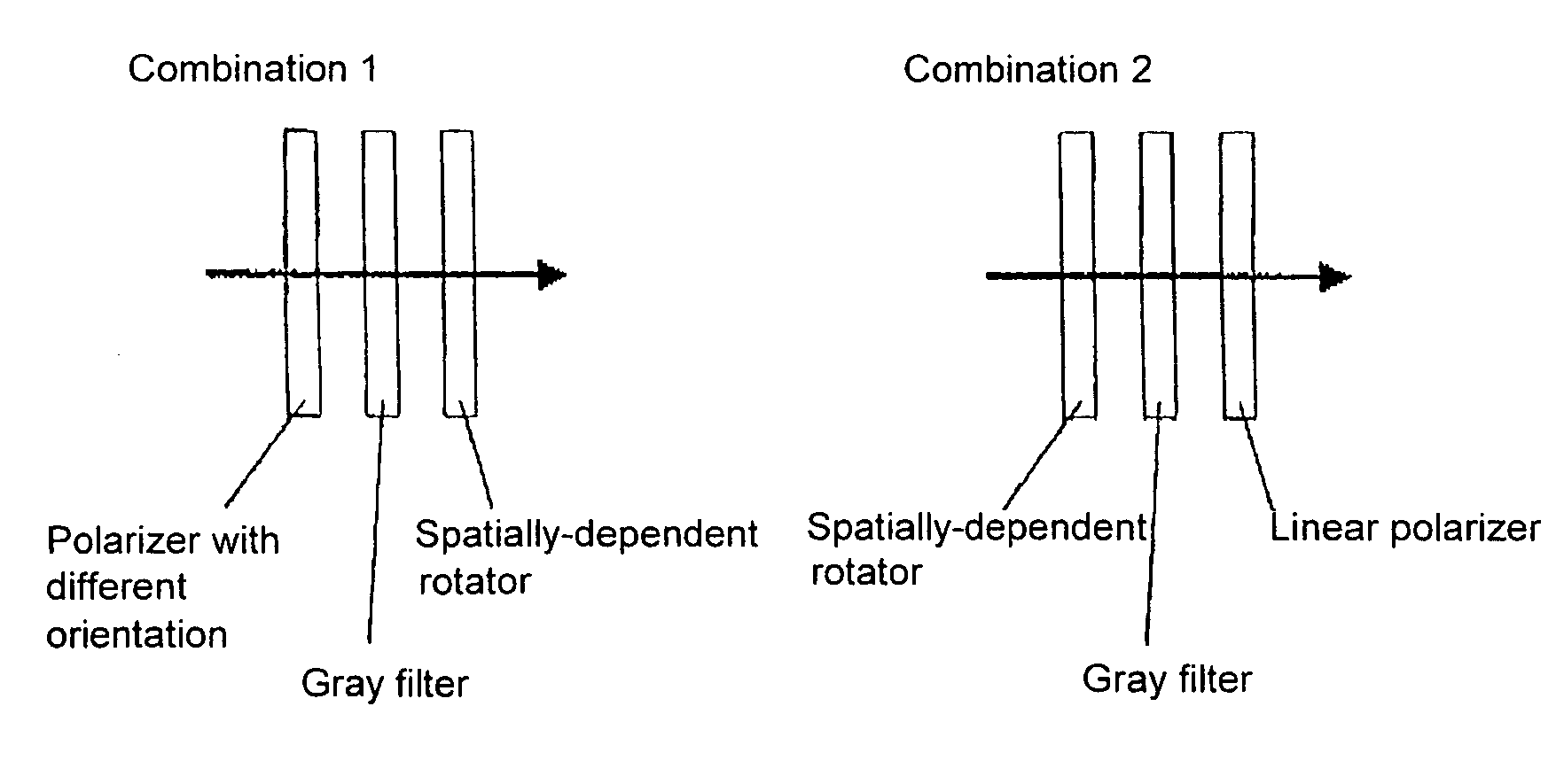
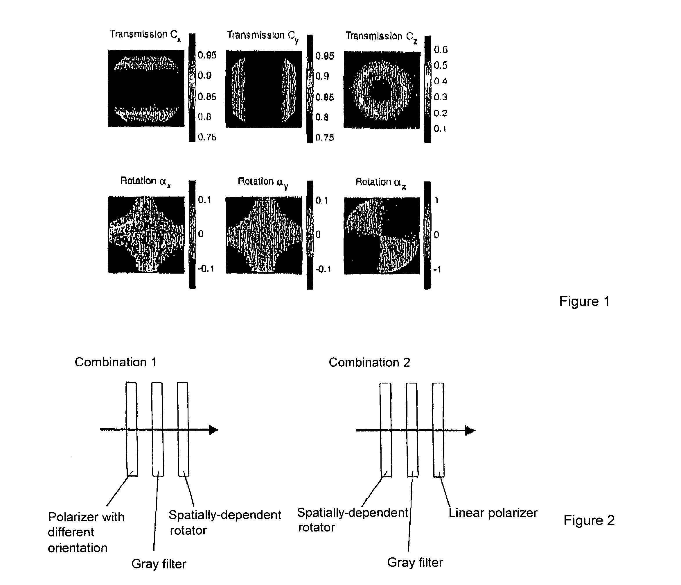
[0024] The microscope imaging system, according to the invention, for emulating high-aperture imaging systems, particularly for mask inspection, comprises imaging optics, a detector and an evaluating unit. Polarization-active optical elements for generating different polarization states of the illumination beam are selectively arranged in the illumination beam path and / or in the imaging beam path for selection of different polarization components of the imaging beam. An optical element with a polarization-dependent intensity attenuation function can be introduced in the imaging beam path. Images of the mask and / or sample are received by the detector for differently polarized beam components. The images for differently polarized beam components are subsequently combined by an evaluating unit to form a total image. This is carried out, for example, by summing their intensity distributions.

[0025] The two-dimensional E-field in the pupil generates a three-dimensional E-field distributi...


PUM


Abstract

The present invention is directed to an optical imaging system for inspection microscopes with which lithography masks can be checked for defects particularly through emulation of high-aperture scanner systems. The imaging system, according to the invention, for emulating high-aperture scanner systems comprises imaging optics, a detector and an evaluating unit, wherein at least one polarization-active optical element is arranged as desired in the imaging beam path for selection of different polarization components of the imaging beam, an optical element with intensity attenuation function can be introduced in the imaging beam path, images of the mask and / or sample are received by the detector for differently polarized beam components and are conveyed to the evaluating unit for further processing. With the proposed solution, it is possible in particular to examine lithography masks for defects in spite of increasingly smaller structures and increasingly higher image-side numerical apertures of the imaging systems by means of inspection microscopes with high magnifications. Realistic images of the stepper systems can be generated by emulating the occurring vector effects.

Description

CROSS-REFERENCE TO RELATED APPLICATION [0001] This application claims priority of German Application No. 10 2004 033 602.4, filed Jul. 8, 2004, the complete disclosure of which is hereby incorporated by reference. BACKGROUND OF THE INVENTION [0002] a) Field of the Invention [0003] The present invention is directed to an optical imaging system for inspection microscopes with which lithography masks can be checked for defects particularly through emulation of high-aperture scanner systems for semiconductor lithography. [0004] b) Description of the Related Art [0005] As object structures continue to decrease in size, increasingly higher image-side numerical apertures of scanner systems are required. However, the incident angles which are therefore also increasingly greater result in vector effects, as they are called, in which tangentially polarized and radially polarized beam components have different intensity curves. It has been shown that the beam components which oscillate perpend...

Claims


Application Information

Patent Timeline
12 Jan 2006
Publication
US20060007541A1
IPC
G02B5/30
CPC
G02B21/002; G03F7/70666; G03F7/70566; G02B27/286
Inventors
TOTZECK, MICHAEL; STROESSNER, ULRICH