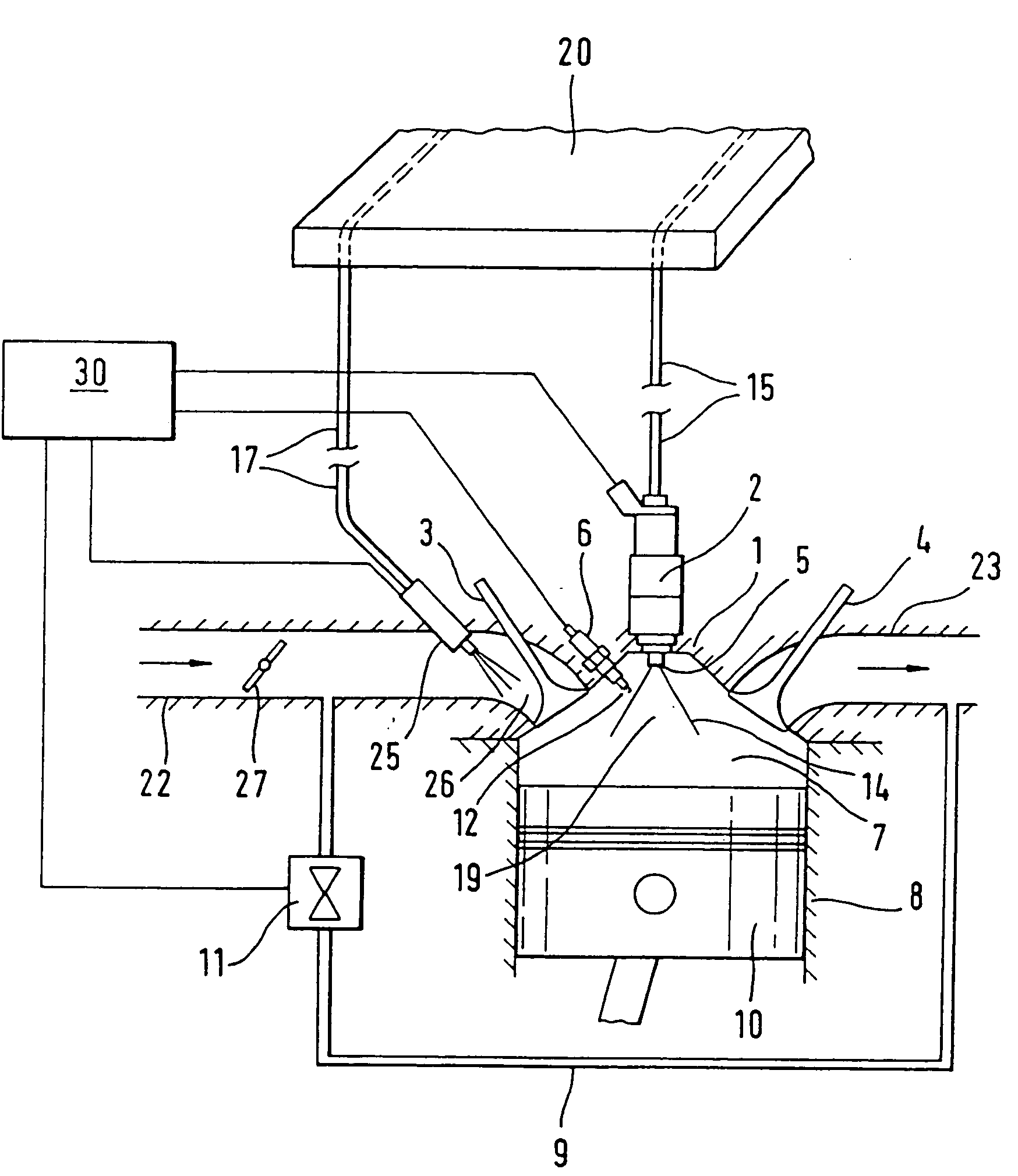
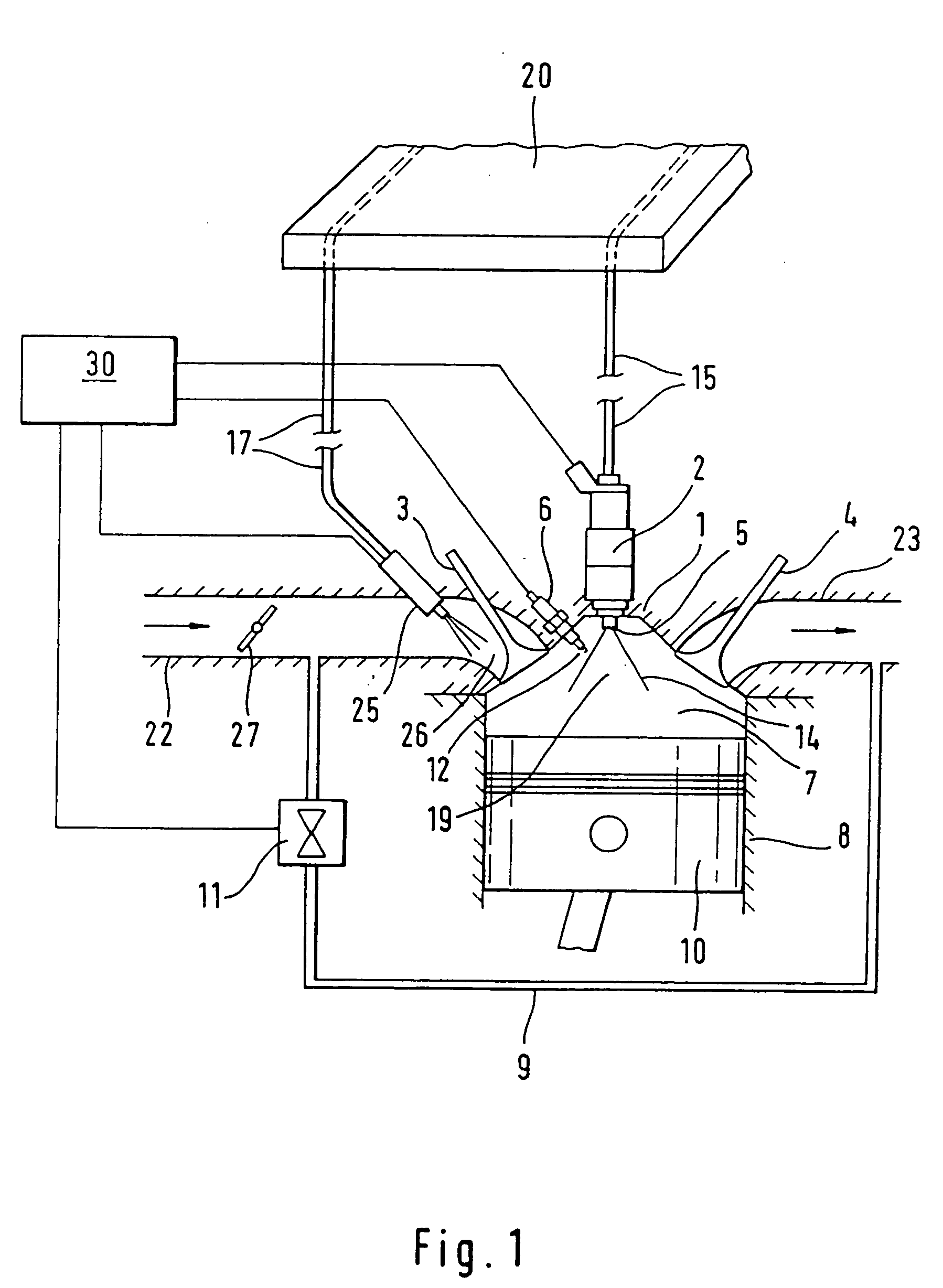
[0007] In a method for operating a spark-ignition internal combustion engine, wherein fuel is metered into the cylinders by direct
fuel injection into the combustion chambers and by the addition of fuel in an intake region of the engine and a
control unit matches the quantity of fuel to be added in the intake region and the quantity of fuel to be injected directly into the combustion chamber to one another as a function of the
operating point of the internal combustion engine so as to provide an ignitable fuel mixture in the combustion chamber, the control unit determines a recirculation rate for the re-circulated exhaust gas and adjusts a predetermined excess air ratio (λ) for the mixture composed of
fresh air, re-circulated exhaust gas and fuel by means of the direct injection of fuel into the combustion chamber taking into account the recirculation rate in order to reduce the exhaust emissions of the internal combustion engine and improve fuel consumption.
[0008] With exhaust gas of the internal combustion engine re-circulated into the intake region, the control unit determines a recirculation rate of the exhaust gas, that is to say the proportion of re-circulated exhaust gas in the fresh gas which is ultimately fed into the combustion chamber. A predefined excess air ratio of the mixture composed of
fresh air, exhaust gas and fuel is adjusted by directly injecting additional fuel into the combustion chamber taking into account the
exhaust gas recirculation rate, with the control unit determining the quantity of fuel to be injected directly into the combustion chamber to provide the internal
mixture formation. As a result of the adjustment of the excess air ratio of the fuel mixture by means of the direct injection of fuel into the combustion chamber, the exhaust gas compatibility of the combustion chamber charge is considerably improved so that, at high recirculation rates, the
exhaust gas emissions of the internal combustion engine can be effectively increased during an operating method with combined metering of fuel by direct
fuel injection into the combustion chamber and additional injection of fuel into the intake region. In this way, high recirculation rates can be combined with the formation of homogenous lean fuel mixtures in the combustion chamber and a low degree of throttling of the internal combustion engine in the partial load range can be achieved, permitting the consumption of fuel to be reduced.
[0009] According to the invention, a lean basic fuel mixture is enriched to the predetermined excess air mixture ratio in the combustion chamber by the direct injection of fuel, while the basic mixture is provided by the admixture of fuel to the intake air in the intake region that is by fuel injection into the intake manifold or by directly injecting fuel into the combustion chamber during the intake
stroke of the internal combustion engine. A high exhaust gas compatibility in the mixture formation is obtained by the direct injection of fuel into the combustion chamber which results in a stabilization of the ignition of lean homogenous mixtures. A stabilizing effect on the ignition of even very lean homogenous fuel mixtures is obtained in particular if the direct injection of fuel for the purpose of achieving the provided excess air ratio in the combustion chamber takes place during the compression cycle.
[0010] A mixture with an excess air ratio in the stoichiometric range of λ=1 is advantageously formed at least in the upper load range of the internal combustion engine, as a result of which lower requirements in terms of exhaust gas treatment can be made even at high fuel
throughput rates. As a result of the ignition injection into the combustion chamber during the compression cycle in combination with the
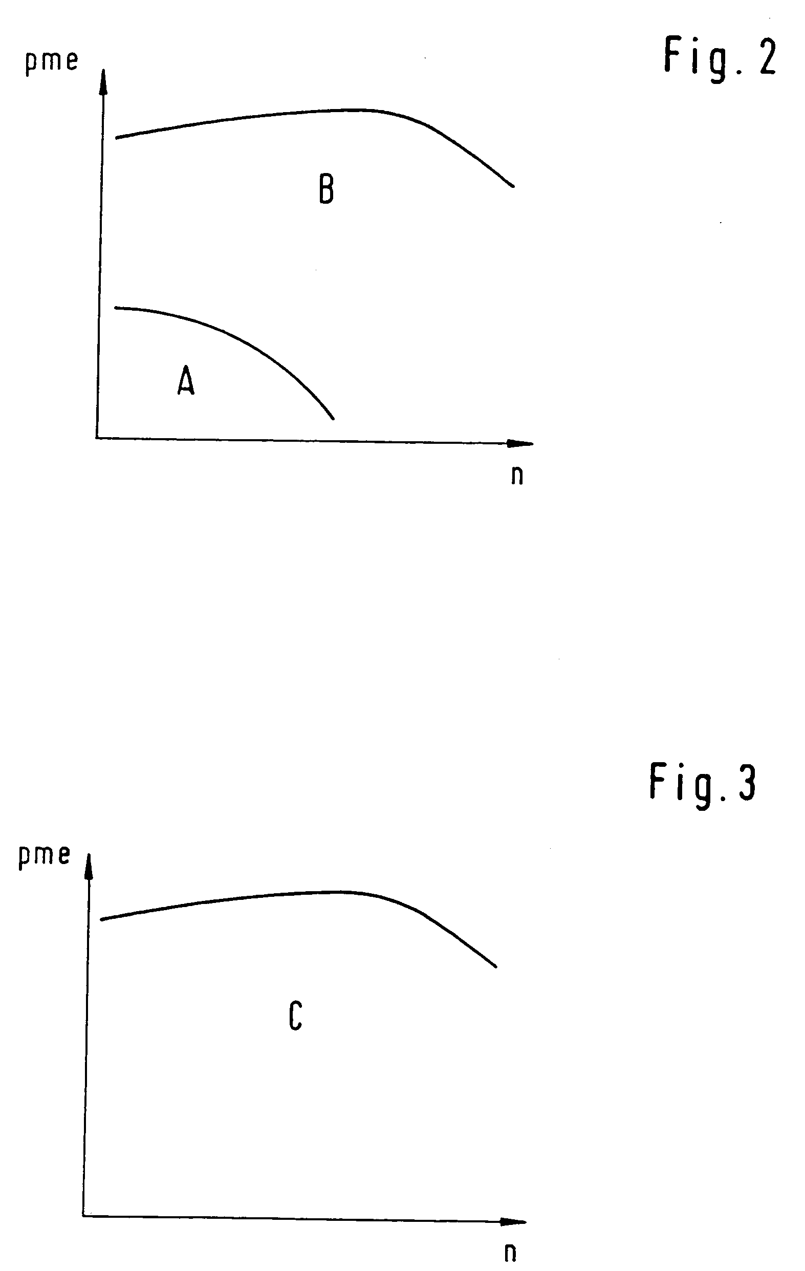
exhaust gas recirculation, consumption advantages are also achieved. In one advantageous embodiment of the invention, the mixture formation is at least carried out predominantly by direct injection of metered fuel amounts into the combustion chamber during the compression
stroke during operation of the internal combustion engine in lower load ranges. At higher operating loads, the
system is switched to mixture formation with enrichment of a lean basic mixture to a stoichiometric excess air ratio by ignition injection. The switching over to the operating mode with stoichiometric mixture formation for higher operating loads is advantageously carried out with an average combustion
chamber pressure of approximately 3.5 bar to 4.5 bar, preferably about 4.0 bar.
[0011] In one alternative embodiment of the invention, the internal combustion engine is operated in the entire load range with mixture formation with excess air coefficients in the stoichiometric range of λ=1. As a result, the necessary devices for the direct metering of fuel into the combustion chambers can be made physically smaller and simpler. Also, advantages can be obtained in terms of the quality of the fuel mixture, and the costs of the
fuel supply system. The fuel consumption of the internal combustion engine can be improved as a result of reduced friction in the injection and metering devices. The operating mode according to the invention with mixture formation in the stoichiometric range over the entire load range of the internal combustion engine also makes it possible to
changeover from previously customary
piston compressors and
piston pumps to cylinder-selective diaphragm compressors, diaphragm pumps or other pump /
nozzle combinations or compressor /
nozzle combinations for the metering of fuel. Furthermore, the direct ignition injection into the combustion chamber during the compression cycle in combination with
exhaust gas recirculation in the full load operating mode of the internal combustion engine results in a turbulence increase in the combustion chamber, which has a positive effect on the
combustion process, allowing the average combustion
chamber pressure to be increased and the exhaust gas temperature to be reduced so that the
exhaust gas emissions can be reduced. The quantity of fuel which is emitted directly into the combustion chamber during the compression cycle (ignition injection) is advantageously less than 20% of the overall quantity of fuel which is to be combusted and which is provided full load engine operation.
