
High pressure resistant vibration absorbing hose and method of producing the same

a high-pressure resistant, hose technology, applied in the direction of flexible pipes, hose connections, mechanical equipment, etc., can solve the problems of interference with other components and parts around the hose, insufficient countermeasures to provide the hose with corrugation, and excessive work load, so as to reduce the effect of repeated pressure or impulse, high pressure resistance, and long service li

Inactive Publication Date: 2006-01-19
SUMITOMO RIKO CO LTD
View PDF6 Cites 29 Cited by
  • Summary
  • Abstract
  • Description
  • Claims
  • Application Information

AI Technical Summary

Benefits of technology

[0044] If the reinforcing layer has a braid or winding angle of the reinforcing wire member larger than the neutral angle, it virtually becomes difficult to diametrically enlarge the axial end portion of the hose or hose body. However, as the hose according to one aspect of the present invention includes the reinforcing layer has a braid or winding angle θ of the reinforcing wire member equal to or lower than the neutral angle, it is possible to diametrically enlarge the axial end portion of the hose body without trouble.
[0051] According to one aspect of the present invention, the mandrel is force fitted in the axial end portion while radially expanding force is exerted in the unvulcanized hose body by applying an internal pressure in the unvulcanized hose body. Thereby the axial end portion may be more easily diametrically enlarged by force fitting of the mandrel.

Problems solved by technology

Therefore, under the circumstances, if a long hose is arranged in the engine room, it bothers an design engineer to design plumbing arrangement to avoid interference with other components or parts and an operator to handle the hose when arranging the hose in the engine room.
These result in excessive work load.
In this instance, when the hose is in a fixed state at opposite ends thereof (usually a hose is applied in this manner), the hose is entirely curved largely and there caused a problem of interference with other components and parts around the hose.
As a conclusion, it is not a sufficient countermeasure to provide the hose with corrugation.
Therefore, resultantly, pressure loss is caused on the portion of the joint fitting during transporting fluid or a required flow amount cannot be secured in such hose.
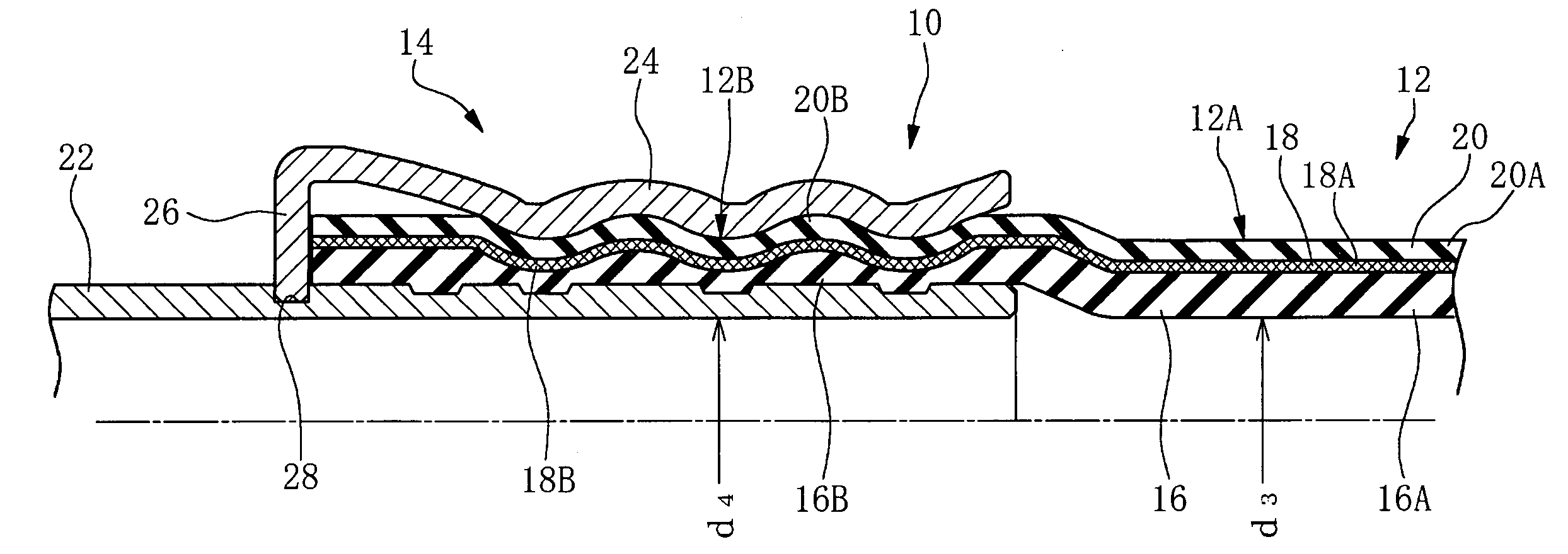
On the other hand, if a hose or hose body is formed with a small diameter at a swaged portion on a hose or hose body end portion and a large diameter joint fitting having an insert pipe with large inner diameter is applied, insertion resistance is extremely increased when the insert pipe is inserted in the swaged portion on the axial end portion, and insertability of the insert pipe is impaired.
Therefore, it is virtually difficult to attach the joint fitting to the swaged portion.
However, in a high density and high-pressure resistant hose that has a bursting pressure equal to or larger than 5 MPa and includes a reinforcing layer with a braid or winding density equal to or larger than 50%, resistance by the reinforcing layer is remarkably increased when the mandrel is inserted in the axial end portion, and diametrically enlarging work is made abruptly difficult.
In case that a hose body is formed first in a straight-walled cylindrical shape and an axial end portion thereof is diametrically enlarged in a later step, there will necessarily be a problem that a wall thickness of the large diameter portion, namely the swaged portion on the axial end portion becomes thin.
If the wall-thickness of the portion to be swaged becomes thin by diametrically enlarging the axial end portion, there occurs a problem that the swaged portion, specifically a swaged portion of the inner surface layer happens to be broken by swaging or compressing operation.
However, in a method of producing the inner surface layer by injection molding, productivity is low, necessarily resulting high production cost.

Method used


Image

  • High pressure resistant vibration absorbing hose and method of producing the same
  • High pressure resistant vibration absorbing hose and method of producing the same
  • High pressure resistant vibration absorbing hose and method of producing the same

Examples


example

[0106] Some example and comparison example hoses or hose bodies are formed or produced having different constructions as shown in Table 1, and each of the hoses or hose bodies is measured and evaluated with respect to insertability of a mandrel, property of a swaged portion, bursting pressure at room temperature (RT), and durability to repeated pressures and high temperature.

[0107] In the line “No. of yarns” of the reinforcing layer of each of example and comparison example hoses or hose bodies in Table 1, “3 parallel yarns×48 carriers”, 2 parallel yarns×48 carriers” mean that 3 or 2 parallel reinforcing yarns of 1000 denier (de) are braided on an 48 carrier machine, and “22 yarns×2 spiraled” means that a strand of 22 reinforcing yarns of 1200 de or 3000 de is wound spirally in one direction to form one ply and another strand of 22 yarns is wound spirally in the reversed direction to laminate another ply over the one ply.

[0108] In Table 1, property of a swaged portion, bursting pr...


PUM

PropertyMeasurementUnit
bursting pressureaaaaaaaaaa
thicknessaaaaaaaaaa
neutral angleaaaaaaaaaa

Abstract

A high pressure resistant vibration absorbing hose with a bursting pressure of 5 MPa or higher has a hose body and a joint fitting. The joint fitting is to be attached to a swaged portion of the hose body. The hose body has an inner surface rubber layer, a reinforcing layer of high braid or winding density of 50% or more, and an outer surface rubber layer. The swaged portion is designed to have a larger diameter than the main portion of the hose body and the inner surface rubber layer has a wall thickness equal to or larger than 1.0 mm at a swaged portion in a state before the joint fitting is securely swaged thereto. The reinforcing layer has a braid or winding angle θ of a reinforcing wire member equal to or lower than a neutral angle 54.7° and higher than 48°.

Description

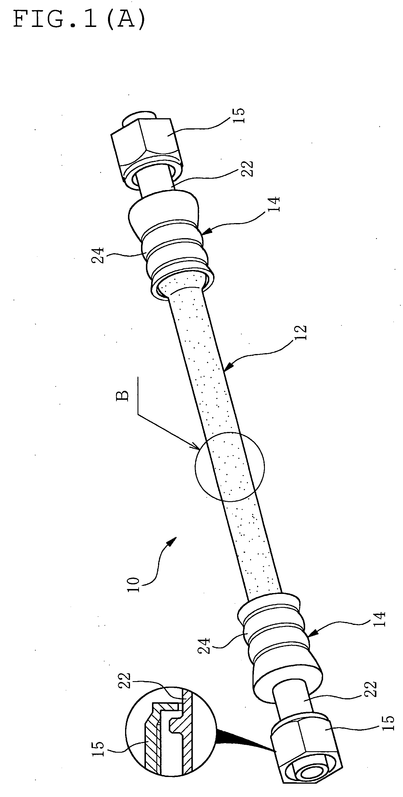
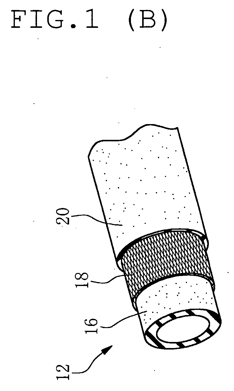
BACKGROUND OF THE INVENTION [0001] The present invention relates to a high pressure resistant vibration absorbing hose, specifically a high pressure resistant vibration absorbing hose to be applied preferably for plumbing in an engine room of a motor vehicle, and a method for producing the same. [0002] Since the past, a hose mainly composed of a tubular rubber layer has been widely used in a variety of industrial and automotive applications. Main purpose of applying such rubber hose is for absorption of vibration. For example, in case of plumbing hose to be arranged in an engine room of a motor vehicle, the plumbing hose serves as to absorb engine vibration, compressor vibration of an air conditioner (in case of a hose for conveying refrigerant, namely an air conditioning hose) and other various vibration generated during car driving, and to restrain transmission of the vibration from one member to the other member which is joined with the one member via the plumbing hose. [0003] Me...

Claims


Application Information

Patent Timeline
Patent Type & Authority Applications(United States)
IPC IPC(8): F16L11/00F16L33/00
CPCF16L11/085
Inventor ARIMA, TETSUYAFURUTA, NORIHIKOIKEMOTO, AYUMU
Owner SUMITOMO RIKO CO LTD
Learn More