Direct-Current Converter

a converter and direct current technology, applied in the direction of electric variable regulation, process and machine control, instruments, etc., can solve the problems of complex enabling control circuits and loss of switching, and achieve the effect of reducing power consumption and reducing switching losses of main switches

Inactive Publication Date: 2006-01-19
SANKEN ELECTRIC CO LTD
View PDF4 Cites 27 Cited by
  • Summary
  • Abstract
  • Description
  • Claims
  • Application Information

AI Technical Summary

Benefits of technology

[0010] It is thus an object of the present invention to provide a direct-current converter whic

Problems solved by technology

However, in the direct-current converter shown in FIG. 1, there has been a problem in that the main switch needs to be turned on at a voltage valley (bott

Method used


Image

  • Direct-Current Converter
  • Direct-Current Converter
  • Direct-Current Converter

Examples


first embodiment

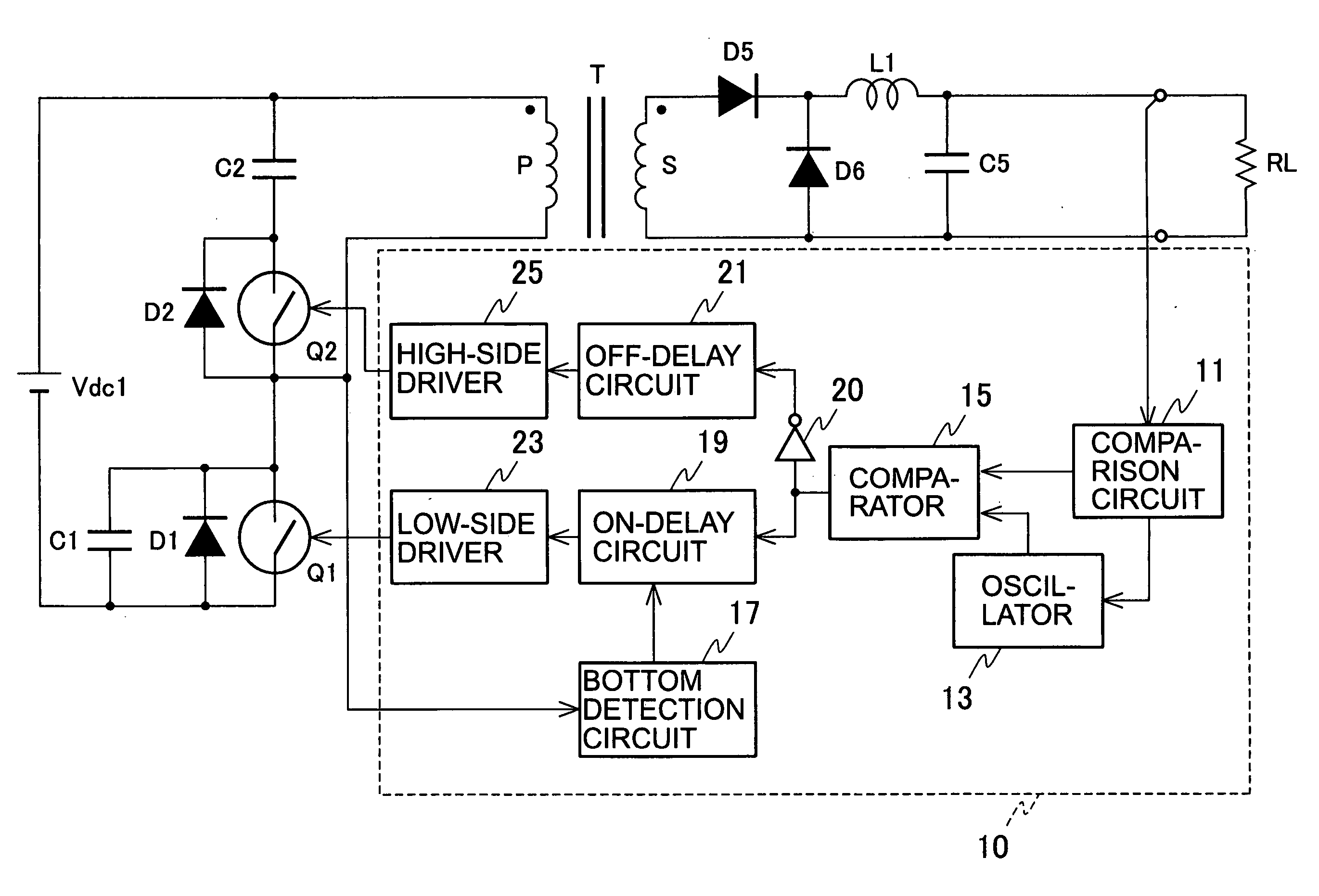
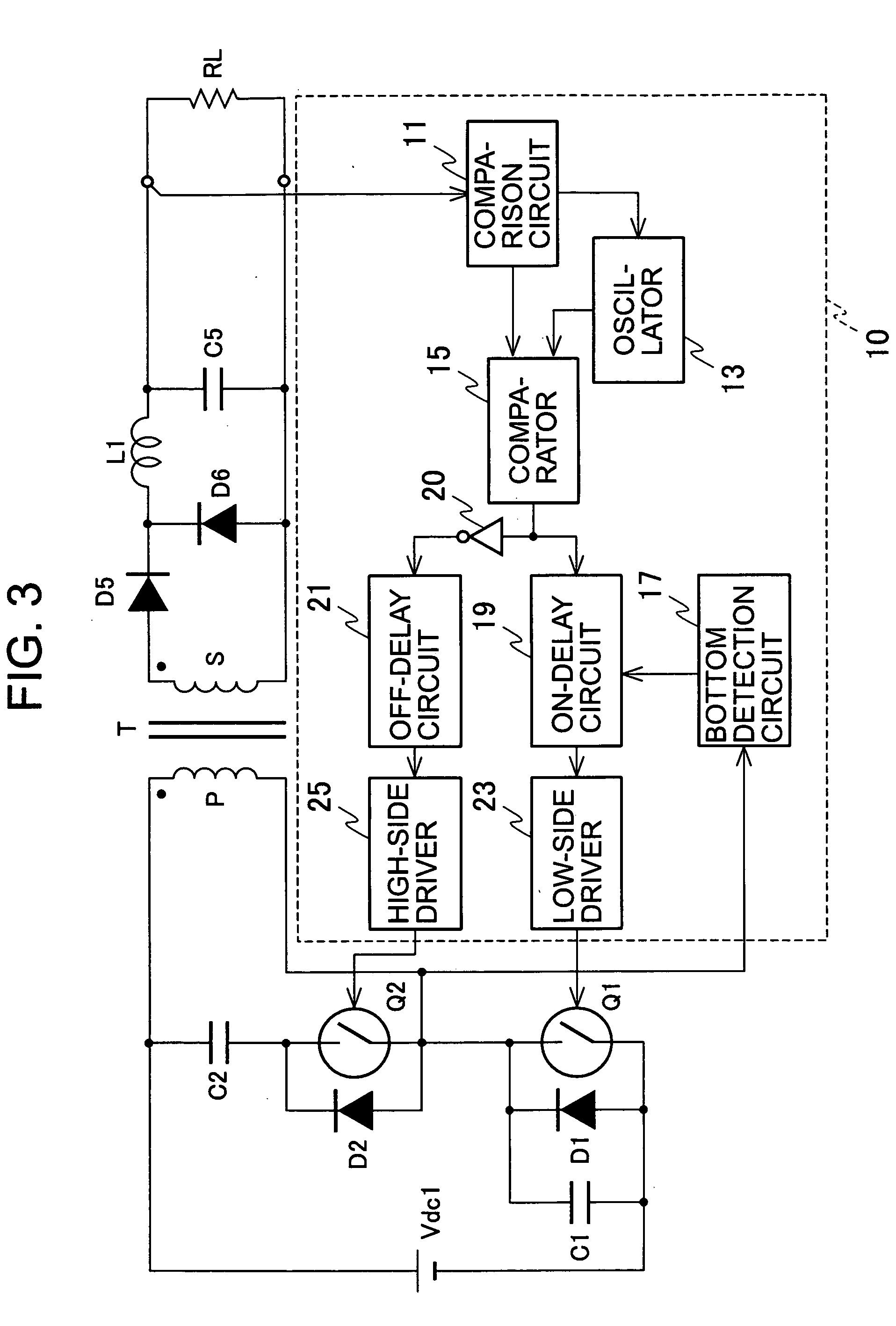
[0033]FIG. 3 is a circuit diagram of a direct-current converter according to the first embodiment. The direct-current converter shown in FIG. 3 uses a so-called active clamp scheme. In the converter, a main switch Q1, including MOSFET or the like, is connected to a direct-current power supply Vdc1 through a primary winding P (winding number: n1) of a transformer T, and a series circuit including an auxiliary switch Q2 made of MOSFET or the like and a snubber capacitor C2 is connected to both ends of the primary winding P. Note that the series circuit including the auxiliary switch Q2 and the snubber capacitor C2 may also be connected to both ends of the main switch Q1 instead of both ends of the primary winding P.

[0034] A parallel circuit including a diode D1 and a capacitor C1 is connected to both ends of the main switch Q1. A diode D2 is connected to both ends of the auxiliary switch Q2. The diode D1 may be a parasitic diode of the main switch Q1 and the diode D2 may be a parasit...

second embodiment

[0064] Next, a direct-current converter according to the second embodiment is described. The direct-current converter of the second embodiment is characterized in that a value of an inductance of a reactor serially connected to a primary winding of a transformer T is increased, and that an auxiliary transformer is provided which causes a reflux of energy, stored in the reactor when the main switch Q1 is turned on, towards the secondary winding side.

[0065]FIG. 12 is a circuit diagram showing the direct-current converter according to the second embodiment. The direct-current converter according to the second embodiment shown in FIG. 12 differs from the direct-current converter according to the first embodiment shown in FIG. 3 in the transformer T and peripheral circuits of the transformer T. Therefore, only these parts are described.

[0066] In this example, an auxiliary transformer is combined with a transformer Tb, and the primary winding P (winding number: n1, also serving as the p...


PUM


Abstract

Provided is a direct-current converter which can reduce power consumption at light load by reducing switching losses of a main switch. The direct-current converter is provided with: a first serial circuit which is connected to both ends of a direct current power supply Vdc1 and in which a primary winding P of a transformer T and a main switch Q1 are serially connected to each other; a second serial circuit which is connected both ends of the primary winding P of the transformer T and in which an auxiliary switch Q2 and a snubber capacitor C2 are serially connected to each other; rectifying/smoothing circuits D5, D6, L1 and C5 which rectify and smooth a voltage generated in a secondary winding S of the transformer T by energy supplied from the primary winding P of the transformer T when the main switch Q1 is turned on; and a control circuit 10 which turns on/off the main switch Q1 and the auxiliary switch Q2 alternately using a signal with predetermined switching frequency. The control circuit 10 reduces the switching frequency during light load.

Description

TECHNICAL FIELD [0001] The present invention relates to a direct-current converter with high-efficiency and low-noise. BACKGROUND ART [0002]FIG. 1 shows a circuit diagram of a conventional direct-current converter of this kind (see Harada, Kosuke. Suicchingu Dengen Handobukku (Switching Power supply Handbook), Chapter 2 Suicchingu Dengen no Kihon Kairo to Sekkei Ensyu (Basic Circuits and Design Practice for Switching Power Supply), p 27, FIG. 2.2, Nikkan Kogyo Shinbun Ltd., and Shimizu, Kazuo. Kosoku Suicching Regyureta (High-Speed Switching Regulator), 2.2.1 Tareigata Konbata (Separately Excited Converter), p 30, FIG. 2.5, Sogo Denshi Syuppan). In the direct-current converter shown in FIG. 1, a main switch Q1, including MOSFET or the like, is connected to a direct-current power supply Vdc1 through a primary winding P (winding number: n1) of a transformer T. A parallel circuit including a resistor R2 and a snubber capacitor C2, and a diode D2 connected in series to this parallel cir...

Claims


Application Information

Patent Timeline
IPC IPC(8): H02M3/335H02M1/34H02M3/28
CPCH02M1/34H02M3/33569Y02B70/16H02M2001/342Y02B70/1491H02M2001/0032Y02B70/10H02M1/0032H02M1/342H02M3/33571H02M3/01
Inventor ASO, SHINJI
Owner SANKEN ELECTRIC CO LTD
Why Eureka
Try Eureka