Method for recording data onto optical recording medium, data recording device, and optical recording medium

a technology of optical recording medium and data recording device, which is applied in the field of an apparatus for recording data in an optical recording medium and an optical recording medium, can solve the problems of insufficient enhancement effect and inability to obtain reproduced signals having a sufficiently high output (modulation) therefrom, and achieve high modulation

Active Publication Date: 2006-01-19
TDK CORPARATION
View PDF27 Cites 53 Cited by
  • Summary
  • Abstract
  • Description
  • Claims
  • Application Information

AI Technical Summary

Benefits of technology

[0016] According to the present invention, when a recording mark is to be formed in at least one information recording layer other than an information recording layer farthest from the light incidence plane, thereby recording data therein, since a laser beam whose power is modulated between at least three levels including a level corresponding to a recording power, a level corresponding to an intermediate power lower than the recording power and a level corresponding to a bottom power lower than the intermediate power is projected onto the at least one information recording layer other than the information recording layer farthest from the light incidence plane to form a recording mark therein, thereby recording data therein, it is possible to control in a desired manner the temperature of the at least one information recording layer other than the information recording layer farthest from the light incidence plane when data are to be recorded therein. Therefore, even in the case where the at least one information recording layer other than the information recording layer farthest from the light incidence plane has no reflective film or only has an extremely thin reflective film and the heat radiation characteristic thereof is low, it is possible to form a recording mark and record data in

Problems solved by technology

In this manner, in an optical recording medium including a plurality of information recording layers, since information recording layers other than the information recording layer farthest from the incidence plane usually have no reflective film or only an extremely thin reflective film, sufficient enhancement ef

Method used


Image

  • Method for recording data onto optical recording medium, data recording device, and optical recording medium
  • Method for recording data onto optical recording medium, data recording device, and optical recording medium
  • Method for recording data onto optical recording medium, data recording device, and optical recording medium

Examples


working example 1

[0187] An optical recording medium sample #1 was fabricated in the following manner.

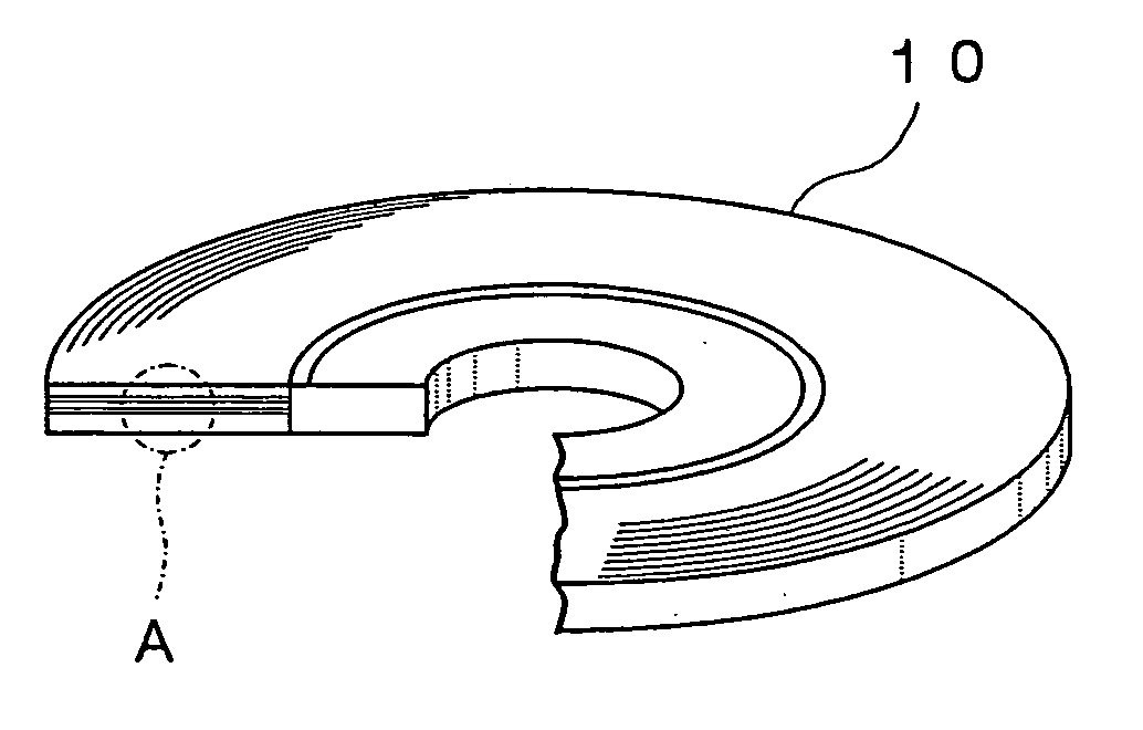
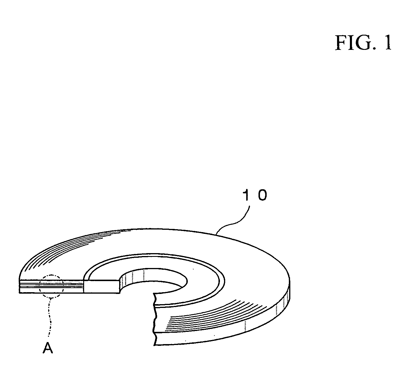
[0188] A disk-like polycarbonate substrate having a thickness of 1.1 mm and a diameter of 120 mm and formed with grooves and lands on the surface thereof was first fabricated by an injection molding process so that the track pitch (groove pitch) was equal to 0.32 μm.

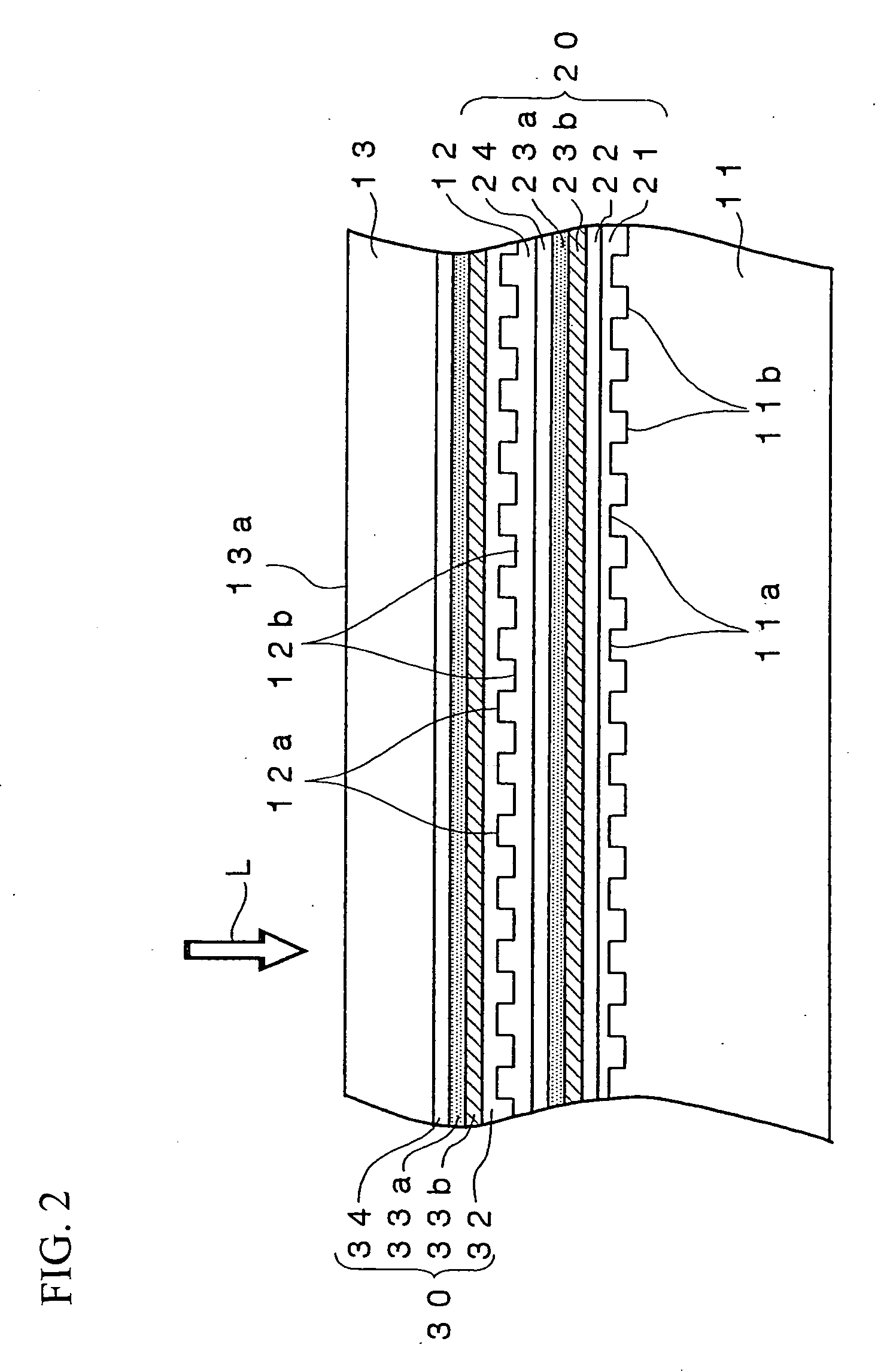
[0189] Then, the polycarbonate substrate was set on a sputtering apparatus and a reflective film consisting of an alloy of Ag, Pd and Cu and having a thickness of 100 nm, a fourth dielectric film containing a mixture of ZnS and SiO2 and having a thickness of 27 nm, a second L0 recording film containing Cu as a primary component, 23 atomic % of Al and 13 atomic % of Au as additives and having a thickness of 5 nm, a first L0 recording film containing Si as a primary component and having a thickness of 5 nm and a third dielectric film containing the mixture of ZnS and SiO2 and having a thickness of 25 nm were sequentially formed on the sur...

working example 2

[0226] The optical recording medium sample # 1 was set in the optical recording medium evaluation apparatus “DDU1000” (Product Name) manufactured by Pulstec Industrial Co., Ltd. and a laser beam having a wavelength λ of 405 nm was focused onto the L0 layer using an objective lens whose numerical aperture was 0.85 via the light transmission layer while the optical recording medium sample # 1 was rotated at a linear velocity of 5.3 m / sec, thereby recording a 2T signal and an 8T signal in the L0 layer of the optical recording medium sample # 1. Here, the power of the laser beam was modulated using the first pulse train pattern.

[0227] The pulse widths of the first pulse train pattern were set so that ttop was equal to 0.7 T, each of tmp and tlp was equal to 0.5T and tcl was equal to 1.0 T.

[0228] The intermediate power Pm of the laser beam was fixed at 2.0 mW and the bottom power thereof was fixed at 0.1 mW while the recording power of the laser beam Pw was varied.

[0229] Then, the 2T ...

working example 3

[0236] The optical recording medium sample # 1 was set in the optical recording medium evaluation apparatus “DDU1000” (Product Name) manufactured by Pulstec Industrial Co., Ltd. and a laser beam having a wavelength λ of 405 nm was focused onto the L0 layer using an objective lens whose numerical aperture was 0.85 via the light transmission layer while the optical recording medium sample # 1 was rotated at the linear velocity of 5.3 m / sec, thereby recording a 2T signal and an 8T signal in the L0 layer of the optical recording medium sample # 1. Here, the power of the laser beam was modulated using the second pulse train pattern.

[0237] The pulse widths of the first pulse train pattern were set so that ttop was equal to 0.7 T and each of tmp and tlp was equal to 0.5T.

[0238] The bottom power thereof was fixed at 0.1 mW while the recording power of the laser beam Pw was varied.

[0239] Then, the 2T signal and the 8T signal recorded in the L0 layer of the optical recording medium sample ...


PUM


Abstract

A method for recording data in an optical recording medium which can record data in information recording layers other than an information recording layer farthest from a light incidence plane of an optical recording medium including a plurality of information recording layers in a desired manner and reproduce data from information recording layers other than the information recording layer farthest from the light incidence plane in a desired manner. The method for recording data in an optical recording medium according to the present invention is adapted for recording data in the optical recording medium including a substrate, a protective layer and a plurality of information recording layers between the substrate and the protective layer by projecting a laser beam onto the plurality of information recording layers via a light incidence plane constituted by either the substrate or the protective layer, thereby recording data in the plurality of information recording layers and the method for recording data in an optical recording medium comprises the steps of projecting a laser beam whose power is modulated between at least three levels including a level corresponding to a recording power, a level corresponding to an intermediate power lower than the recording power and a level corresponding to a bottom power lower than the intermediate power onto at least one information recording layer other than an information recording layer farthest from the light incidence plane and forming a recording mark in the at least one information recording layer other than the information recording layer farthest from the light incidence plane, thereby recording data therein.

Description

BACKGROUND OF THE INVENTION [0001] 1. Field of the Invention [0002] The present invention relates to a method for recording data in an optical recording medium, an apparatus for recording data in an optical recording medium and an optical recording medium and particularly, to a method for recording data in an optical recording medium and an apparatus for recording data in an optical recording medium which can record data in information recording layers other than an information recording layer farthest from a light incidence plane of an optical recording medium including a plurality of information recording layers in a desired manner and reproduce data from information recording layers other than the information recording layer farthest from the light incidence plane in a desired manner, and an optical recording medium which includes a plurality of information recording layers and can record data in information recording layers other than an information recording layer farthest from...

Claims


Application Information

Patent Timeline
IPC IPC(8): G11B7/00G11B7/0045G11B7/125G11B7/135G11B7/24G11B7/243
CPCG11B7/00456G11B7/24038G11B7/243G11B2007/0013G11B7/258G11B7/2585G11B7/2534
Inventor INOUE, HIROYASUKATO, TATSUYAKAKIUCHI, HIRONORI
Owner TDK CORPARATION
Why Eureka
Try Eureka