
Pulse mode modulation in frequency converted laser sources

a laser source and pulse mode technology, applied in semiconductor lasers, optics, instruments, etc., can solve the problems of significant electronic limitations of generating such high-speed modulation signals, high-speed analog circuits that often require costly components and design and manufacturing techniques, so as to improve conversion efficiency, optimize electrical power efficiency, and achieve high modulation

Inactive Publication Date: 2011-04-05
CORNING INC
View PDF9 Cites 5 Cited by
  • Summary
  • Abstract
  • Description
  • Claims
  • Application Information

AI Technical Summary

Benefits of technology

The present patent relates to improving the efficiency of frequency-converted green lasers used in scanning-type laser projection systems. The technical effect of the patent is to provide a novel high-speed modulation scheme that optimizes the conversion efficiency of the green laser sources while meeting the requirements of high dynamic range and resolution. The proposed modulation scheme is a continuous modulation scheme that retains the efficiency of basic PWM modulation while achieving full dynamic range. The method includes driving the laser diode in a pulsed mode to define pixel intensity values corresponding to desired gray scale values of image pixels. The pulse width of the discontinuous pulse component is selected based on the desired pixel gray scale value and the contributions of the relatively constant intensity component and the pulse width to pixel intensity. The continuous modulation scheme is particularly useful for applications requiring high modulation rates and minimal pulse durations.

Problems solved by technology

However, many applications require modulation rates greater than 2 Ghz, which requires very narrow pulses in the laser signal.
Even though class-leading IR lasers have impressive modulation capabilities, there would be significant electronic limitations for generating such high speed modulation signals.
Specifically, high intensity seed lasers require high currents to generate desired output levels and state of the art on-off current drivers that meet the current requirement of such high intensity lasers typically have rise and fall times of 1 to 2 ns—a factor that can significantly limit the modulation speed of a compact laser.
Alternatively to achieve the combination of high modulation speed and extinction ratio, high speed analog circuits often require costly components and design and manufacturing techniques.
Considering these practical limitations, a traditional PWM scheme would suffer from reduced image resolution or limited dynamic range.

Method used


Image

  • Pulse mode modulation in frequency converted laser sources
  • Pulse mode modulation in frequency converted laser sources
  • Pulse mode modulation in frequency converted laser sources

Examples


Embodiment Construction

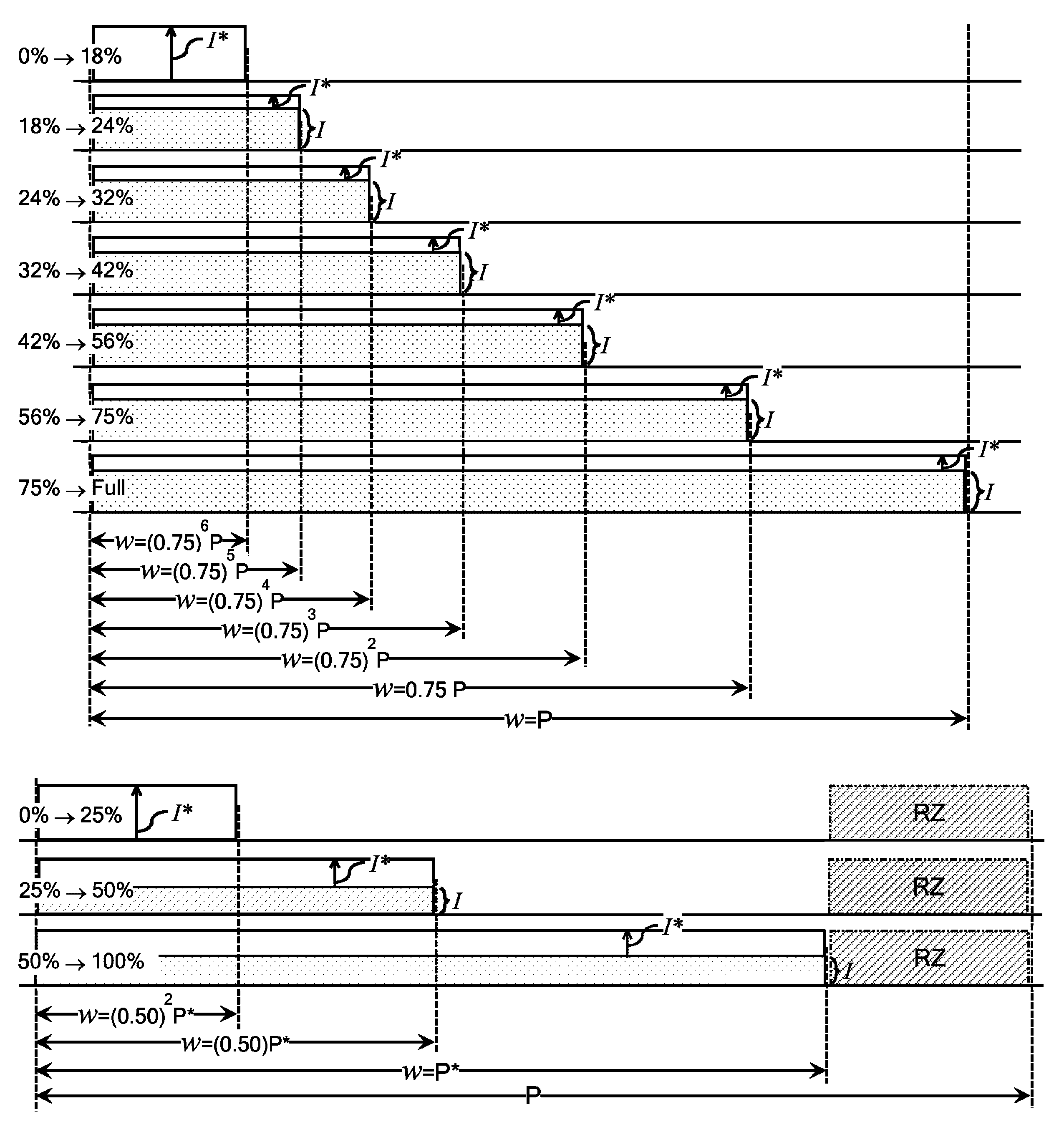
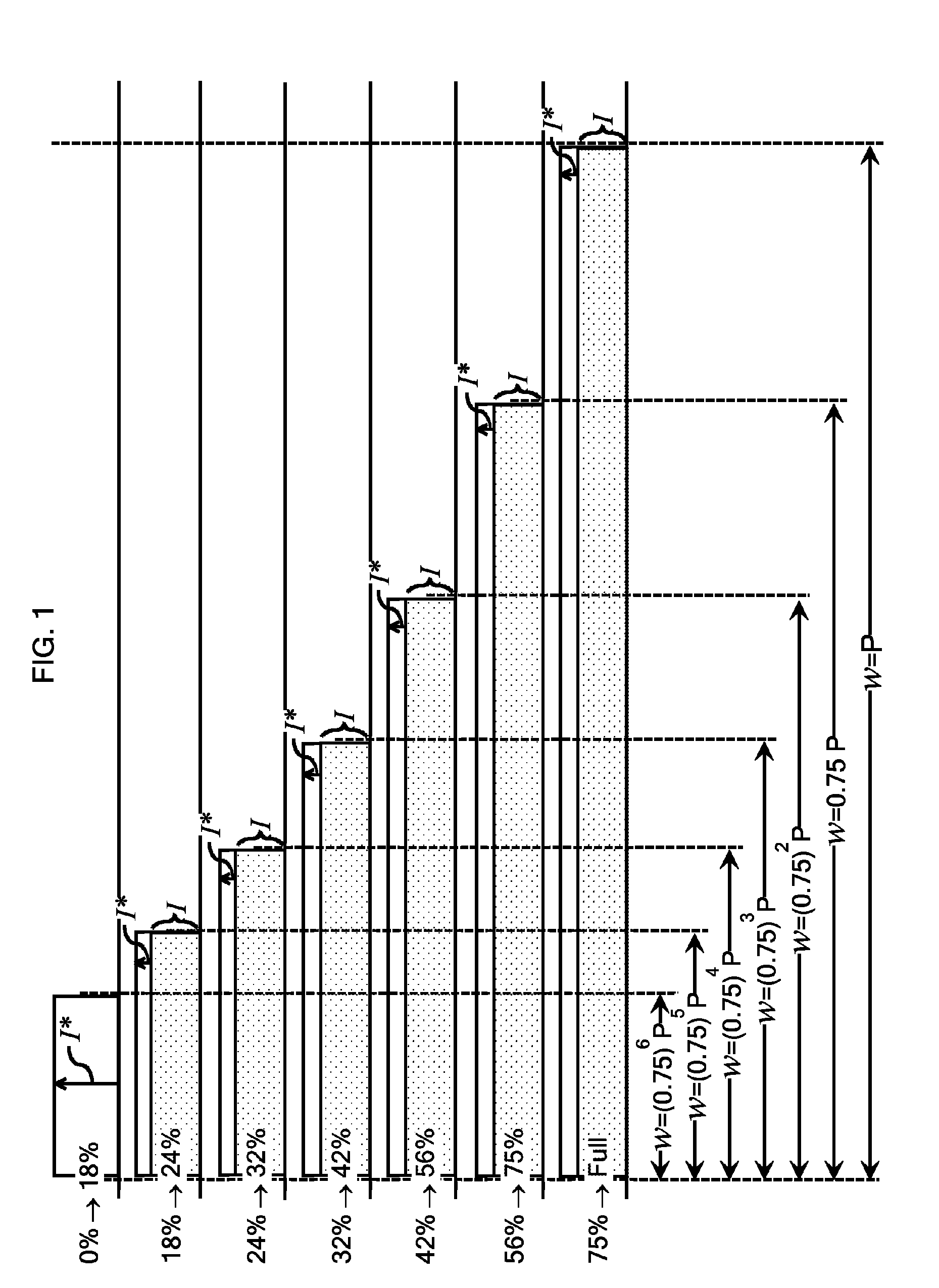
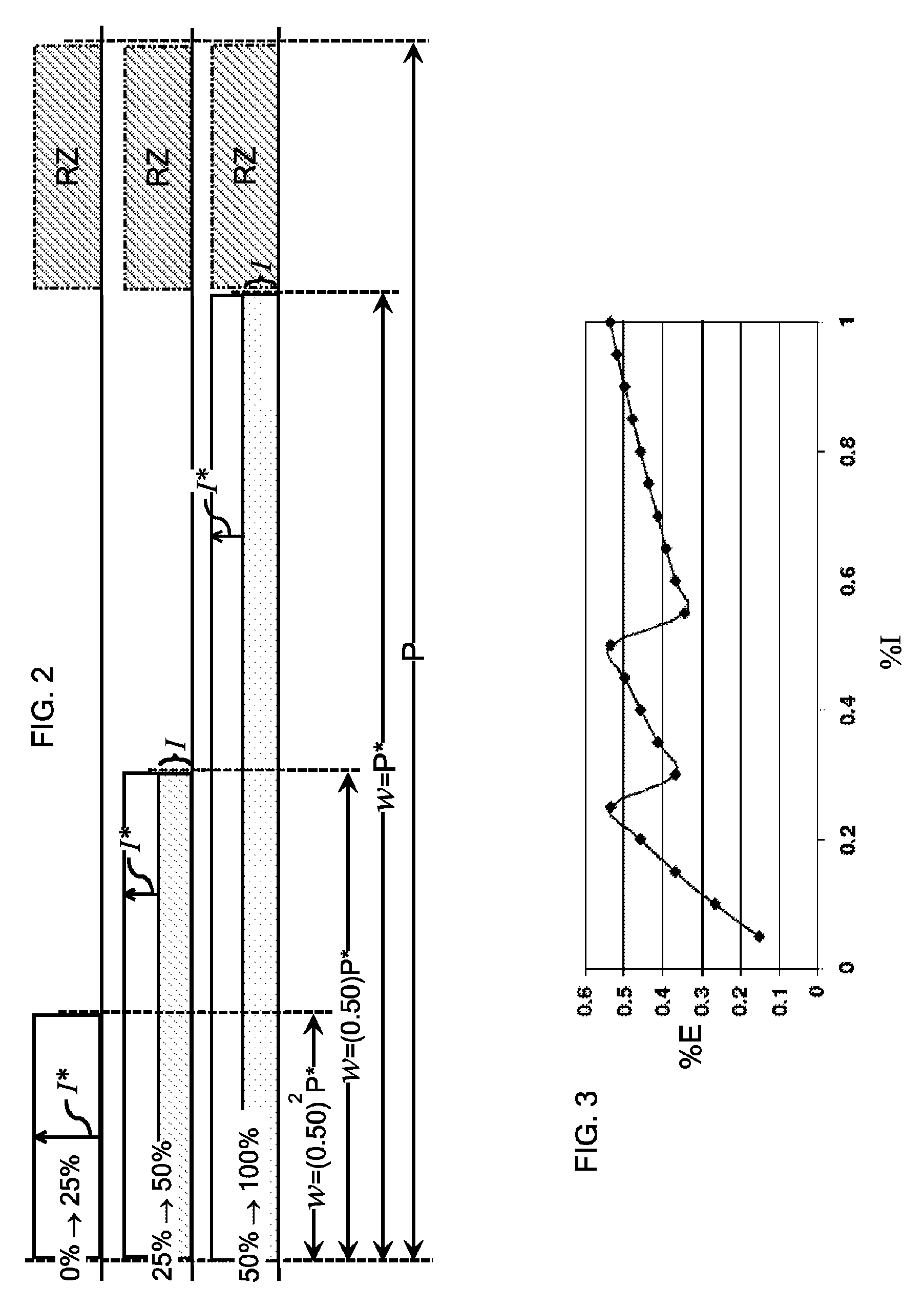
One of the contemplated operational methods of the present disclosure can be illustrated with reference to the diagram of FIG. 1 and the frequency converted laser source 100 of FIG. 6, which typically comprises a laser diode 10 that is optically coupled to a wavelength conversion device 20 for conversion of a pulsed optical signal generated by the laser diode 10. They laser source may also comprise a variety of additional components including, for example, coupling optics 30, collimating optics 40, and an optical filter 50.

According to the illustrated method, the laser diode 10 is driven in a pulsed mode to define pixel intensity values that correspond to desired gray scale values of image pixels in the image plane of the laser source 100. The pixel intensity values are a function of a laser control signal that comprises a discontinuous pulse component of pulse width w, a relatively constant intensity component I, and a continuously variable intensity component I*; each of which are...


PUM


Abstract

Methods of operating a frequency-converted laser source are disclosed. According to particular disclosed embodiments, a laser diode is driven in a pulsed mode to define pixel intensity values corresponding to desired gray scale values of image pixels in an image plane of the laser source. The pixel intensity values are a function of a laser control signal comprising a discontinuous pulse component, a relatively constant intensity component I, and a continuously variable intensity component I*. The pulse width w of the discontinuous pulse component is selected from a set of discrete available pulse widths according to a desired pixel gray scale value. A low-end pulse width w of the set of available pulse widths is established for a range of low-end pixel gray scale values and progressively larger pulse widths w are established for ranges of progressively higher pixel gray scale values. The relatively constant intensity component I makes a relatively insignificant contribution to pixel intensity at the low-end pulse width w for the range of low-end pixel gray scale values and assumes a non-zero value for enhanced conversion efficiency at the progressively larger pulse widths w established for the higher pixel gray scale values. The continuously variable intensity component I* varies according to the desired gray scale value of the selected pixel and the contributions of the relatively constant intensity component I and the pulse width w to pixel intensity.

Description

BACKGROUND1. Field of the DisclosureThe present disclosure relates to frequency-converted laser sources and, more particularly, to frequency-converted laser sources.2. Technical BackgroundThe present invention relates generally to semiconductor lasers, which may be configured in a variety of ways. For example and by way of illustration, not limitation, short wavelength sources can be configured for high-speed modulation by optically coupling the output of a semiconductor laser with the waveguide of a light wavelength conversion device, such as a second harmonic generation (SHG) crystal. The SHG crystal can be configured to generate higher harmonic waves of the fundamental laser signal by tuning, for example, a 1060 nm DBR or DFB laser to the spectral center of a SHG crystal, which converts the wavelength to 530 nm. However, the wavelength conversion efficiency of an SHG crystal, such as MgO-doped periodically poled lithium niobate (PPLN), is strongly dependent on the intensity of th...

Claims


Application Information

Patent Timeline
Patent Type & Authority Patents(United States)
IPC IPC(8): H01S3/13
CPCH04N9/3129H01S5/06216H01S5/0092H01S5/06256
Inventor LOEBER, DAVID AUGUST SNIEZEKSEKIGUCHI, NOBUTOSHIRICKETTS, DANIEL OHEN
Owner CORNING INC
Learn More