Apparatus and method for controlling kinetic rates for internal reforming of fuel in solid oxide fuel cells

a solid oxide fuel cell and internal reforming technology, applied in the field of apparatus and method for controlling internal reforming kinetic rate in solid oxide fuel cells, can solve the problems of slow reaction rate, achieve the effects of increasing rate, promoting reforming, and slowing reaction ra

Active Publication Date: 2006-01-19
FORD MOTOR CO
View PDF13 Cites 12 Cited by
  • Summary
  • Abstract
  • Description
  • Claims
  • Application Information

AI Technical Summary

Benefits of technology

[0008] The present invention overcomes one or more problems of the prior art by providing in at least one embodiment a solid oxide fuel cell in which kinetic rates for internal reforming are controlled. The solid oxide fuel cell of the invention comprises a cathode, an electrolyte layer adjacent to the cathode, and an anode adjacent to the electrolyte layer. Moreover, the cathode, electrolyte layer, and the anode may be arranged in a planar configuration or in a concentric configuration. The anode used in the cell of the invention includes a support structure which defines at least a portion of an anode flow channel and a catalyst that promotes reforming. The anode flow channel has an anode flow channel entrance for the introduction of fuel to the solid oxide fuel cell and an anode flow channel exit for removing unreacted fuel and / or by-products. The catalyst is dispersed within or upon the support structure such that the rate of reforming increases at increasing distances from the anode flow channel entrance. By increasing the catalyst concentration in the direction of fuel flow you are “effectively” spreading the hydrocarbon conversion along the flow direction since the rate of reforming is proportional to the catalyst concentration. Once the reforming starts, the hydrocarbon concentration will drop along the flow direction, which will also slow the reaction rate. This drop in hydrocarbon concentration will allow the catalyst concentration to be raised to a higher value in the fuel downstream direction. Typically, this increasing rate is achieved by providing a catalyst concentration profile in which the catalyst has a first concentration at a first position and a second concentration at a second position such that the first position is closer to the anode flow channel entrance than the second position and the first concentration is lower than the second concentration. Although the regions of the anode having lower catalyst concentration will have a lower electronic conductivity, the electrolyte layer is typically the dominant contributor to cell resistivity (by several orders of magnitude). Accordingly, a large drop in anode conductivity can be tolerated.

Problems solved by technology

Once the reforming starts, the hydrocarbon concentration will drop along the flow direction, which will also slow the reaction rate.

Method used


Image

  • Apparatus and method for controlling kinetic rates for internal reforming of fuel in solid oxide fuel cells
  • Apparatus and method for controlling kinetic rates for internal reforming of fuel in solid oxide fuel cells
  • Apparatus and method for controlling kinetic rates for internal reforming of fuel in solid oxide fuel cells

Examples


Embodiment Construction

[0017] The following examples illustrate the various embodiments of the present invention. Those skilled in the art will recognize many variations that are within the spirit of the present invention and scope of the claims.

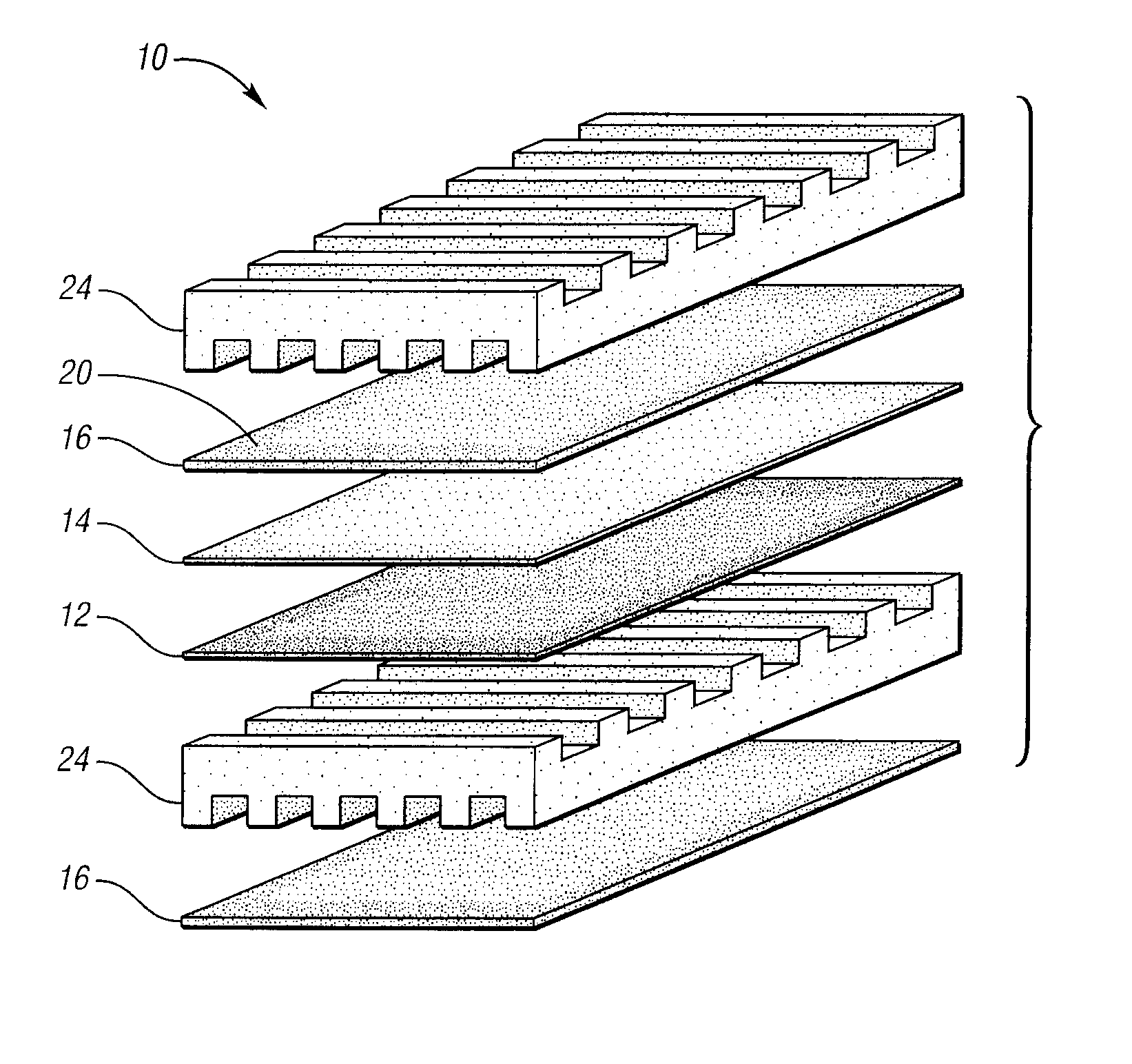
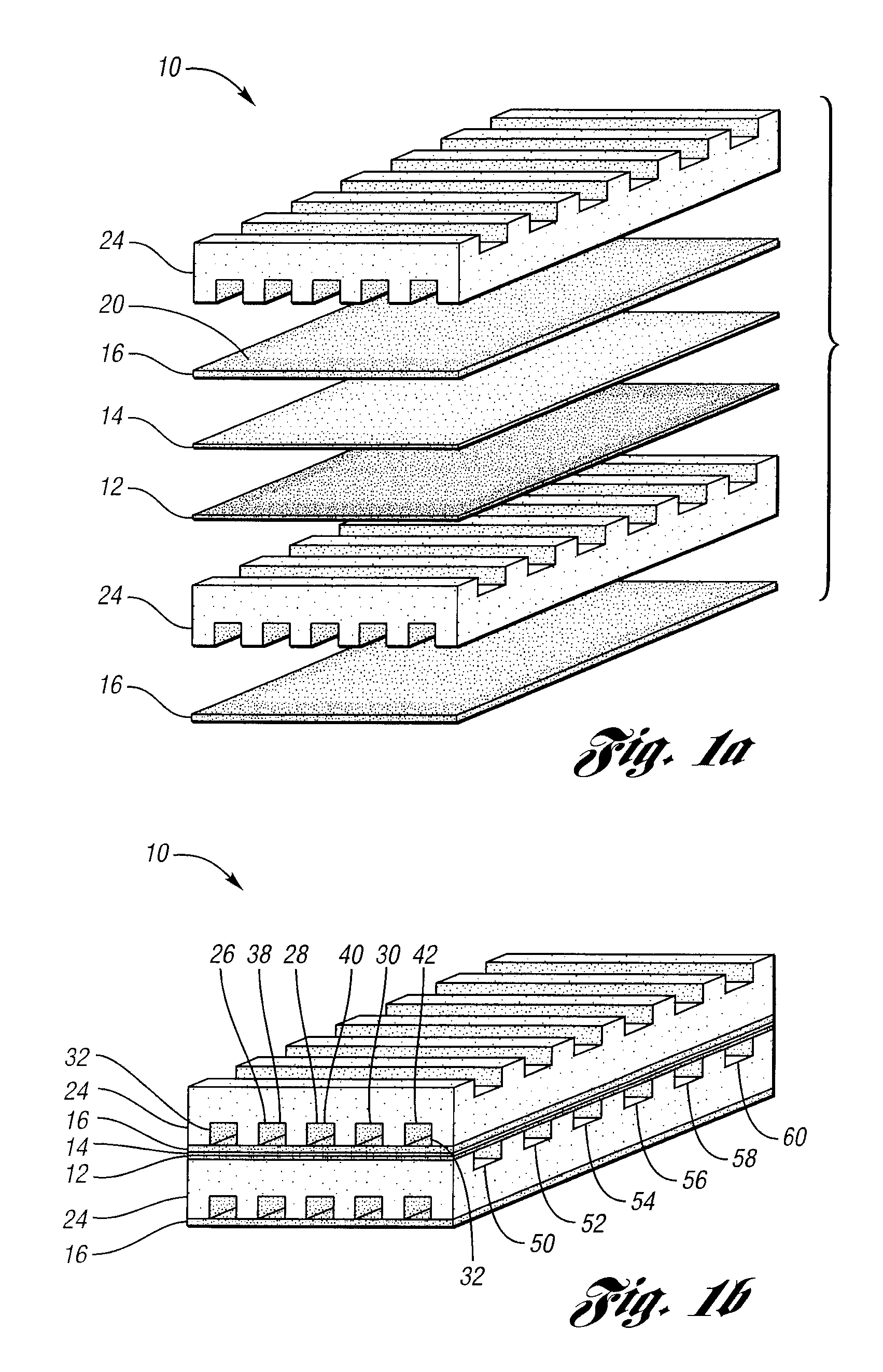
[0018] In one embodiment of the present invention, a solid oxide fuel cell is provided. With reference to FIGS. 1A and B, schematics of a solid oxide fuel cell in which the anode, cathode, and electrolyte layer are arranged in substantially parallel sheets are provided. Solid oxide fuel cell 10 includes cathode 12, electrolyte layer 14 adjacent to cathode 12, and anode 16 adjacent to electrolyte layer 14. Anode 16 is made from support structure 20. Support structure as used herein means the solid material from which the anode is made. Anode 18 also includes a catalyst that promotes reforming. Accordingly, anode 18 is typically combination of a metal catalyst and a ceramic material. Such a compound structure is referred to a cermet. Typically, the anode layer in s...


PUM

PropertyMeasurementUnit
thicknessaaaaaaaaaa
thicknessaaaaaaaaaa
thicknessaaaaaaaaaa

Abstract

The present invention provides a solid oxide fuel cell in which kinetic rates for internal reforming are controlled. The solid oxide fuel cell comprises a cathode, an electrolyte layer adjacent to the cathode, and an anode adjacent to the electrolyte layer. The anode used in the cell of the invention includes a support structure which defines at least a portion of an anode flow channel and a catalyst that promotes reforming. The anode flow channel has an anode flow channel entrance for the introduction of fuel to the solid oxide fuel cell and an anode flow channel exit for removing unreacted fuel and / or by-products. The catalyst is dispersed within or upon the support structure such that the rate of reforming increases at increasing distances from the anode flow channel entrance. The present invention also provides a method of controlling internal reforming kinetic rates in a solid oxide fuel cell.

Description

BACKGROUND OF INVENTION [0001] 1. Field of the Invention [0002] The present invention relates to an apparatus and method for controlling internal reforming kinetic rates in a solid oxide fuel cell. [0003] 2. Background Art [0004] Fuel cells are electrochemical devices that convert the chemical energy of a fuel into electricity and heat without fuel combustion. In the one type of fuel cell hydrogen gas and oxygen gas are electrochemically combined to produce electricity. The hydrogen used in this process may be obtained from natural gas or methanol while air provides the oxygen source. The only by-products of this process are water vapor and heat. Accordingly, fuel cell-powered electric vehicles reduce emissions and the demand for conventional fossil fuels by eliminating the internal combustion engine (e.g., in completely electric vehicles) or operating the engine at only its most efficient / preferred operating points (e.g., in hybrid electric vehicles). However, while fuel cell-power...

Claims


Application Information

Patent Timeline
Patent Type & Authority Applications(United States)
IPC IPC(8): H01M8/00H01M8/10H01M2/00
CPCC01B3/38C01B2203/0227C01B2203/066C01B2203/1058C01B2203/1082Y02E60/525H01M8/0637H01M8/1213H01M2008/1293Y02E60/521H01M4/8642Y02E60/50
Inventor ELLWOOD, KEVINHARRIS, STEPHEN
Owner FORD MOTOR CO
Why Eureka
Try Eureka