Apparatus and method for preventing overheating of exhaust purification filter

a technology apparatus, which is applied in mechanical apparatus, electrical control, machines/engines, etc., can solve the problems of exhaust purification filter overheating or deterioration, and the exhaust purification filter is more likely to overheat, so as to effectively prevent the exhaust purification filter of an internal combustion engine from overheating

Inactive Publication Date: 2006-01-26
TOYOTA JIDOSHA KK
View PDF10 Cites 45 Cited by
  • Summary
  • Abstract
  • Description
  • Claims
  • Application Information

AI Technical Summary

Benefits of technology

[0007] Accordingly, it is an objective of the present invention to provide an apparatus that effe

Problems solved by technology

Some of the heat generated during the regeneration of the exhaust purification filter is lost to the outside.
Thus, if the internal combustion engine is decelerated during the temperature increase process for regenerating the filter, heat is accumulated in the filter,

Method used


Image

  • Apparatus and method for preventing overheating of exhaust purification filter
  • Apparatus and method for preventing overheating of exhaust purification filter
  • Apparatus and method for preventing overheating of exhaust purification filter

Examples


first embodiment

[0084] The first embodiment described above has the following advantages.

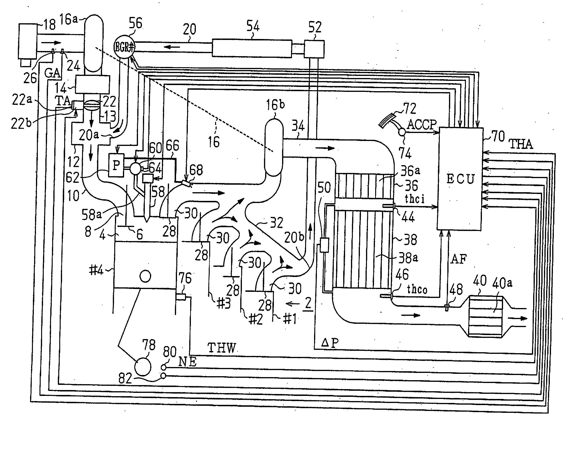
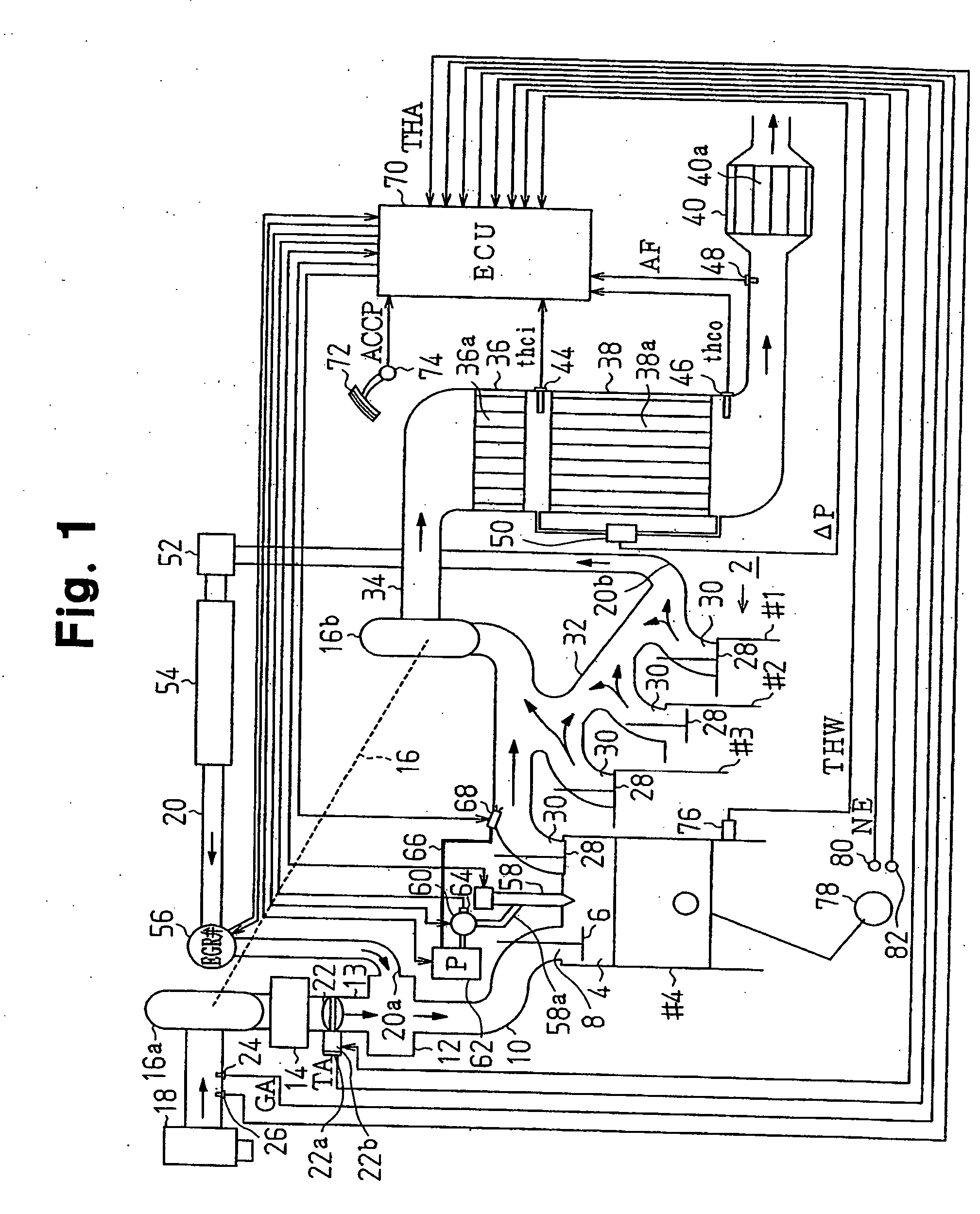
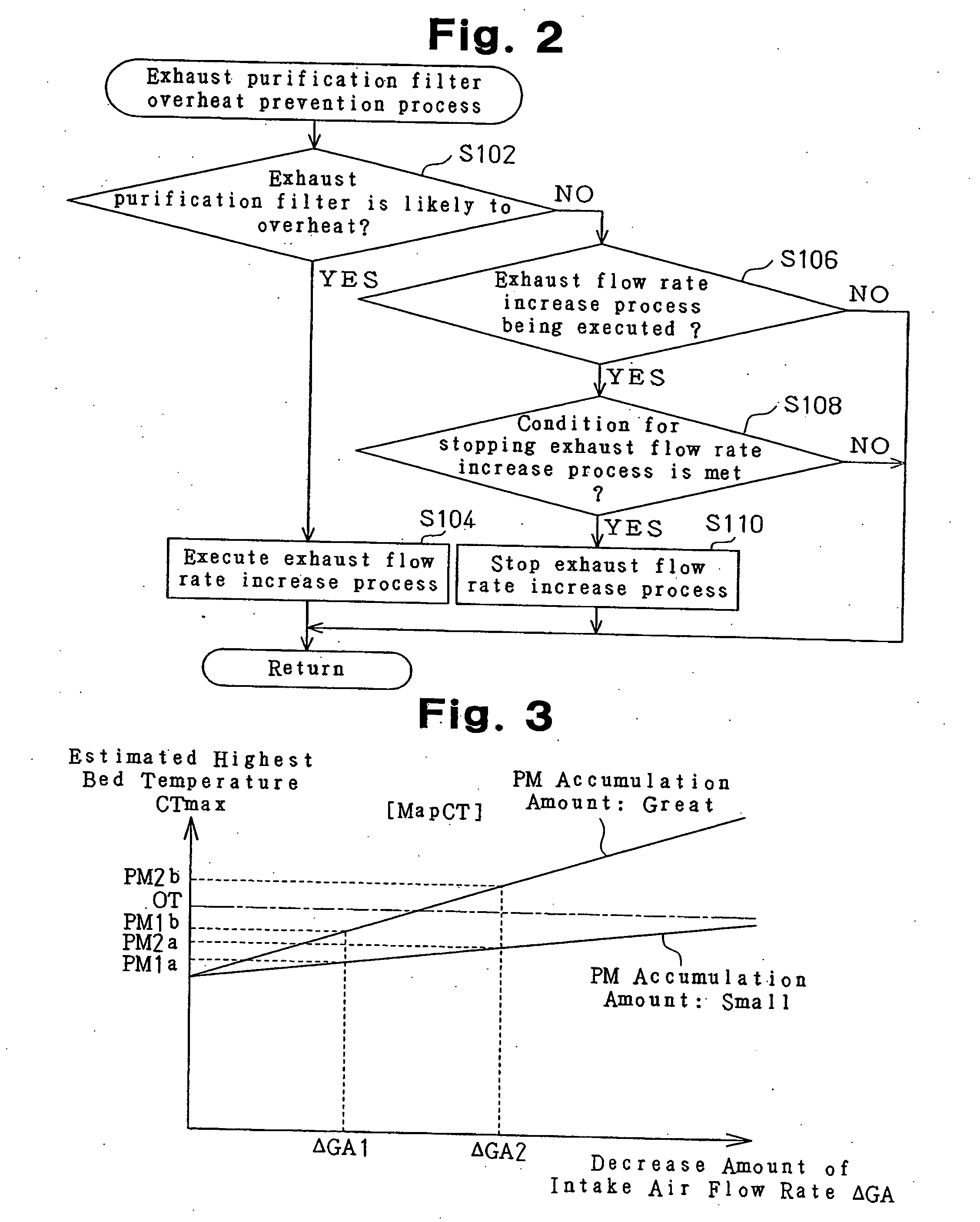
[0085] (A1) In the overheat prevention process of FIG. 2, when the exhaust purification filter 38a is likely to overheat, the throttle valve 22 is fully opened, and the EGR valve 56 is fully closed. Accordingly, the intake flow rate and the exhaust flow rate are increased. Then, when steps S156, S160 of the fuel injection amount control of FIG. 5 are executed, the idle speed is increased during idling. A sufficient exhaust flow rate is thus ensured. Therefore, the heat generated in the exhaust purification filter 38a is positively lost to the outside, and the exhaust purification filter 38a is effectively prevented from overheating.

[0086] (A2) Whether the exhaust purification filter 38a is likely to overheat is determined by monitoring whether the expected maximum bed temperature CTmax, which is estimated based on the map MapCT of FIG. 3, exceeds the overheat determination temperature OT based on the intake fl...

second embodiment

[0096] The second embodiment as described above has the following advantages.

[0097] (A1) The second embodiment has the same advantage as the item (A1) of the first embodiment.

[0098] (A2) Whether the exhaust purification filter 38.a is likely to overheat is determined based on the upstream exhaust temperature thci detected by the first exhaust temperature sensor 44 and the downstream exhaust temperature thco detected by the second exhaust temperature sensor 46.

[0099] The temperature of the exhaust purification filter 38a is affected by the temperature of exhaust gas that flows into the filter 38a. Therefore, whether the exhaust purification filter 38a is likely to overheat can be determined by determining the upstream exhaust temperature thci of the exhaust purification filter 38a.

[0100] Particularly, the NOx storage reduction catalyst 36a, which is another exhaust purification catalyst, is disposed in a section upstream of the exhaust purification filter 38a. The NOx storage redu...

third embodiment

[0115] The third embodiment as described above has the following advantages.

[0116] (A1) The third embodiment has the same advantage as the item (A1) of the first embodiment.

[0117] (A2) Whether the exhaust purification filter 38a is likely to overheat is determined based on the estimated bed temperature thcf estimated based on the intake flow rate GA, the amount of added fuel, and the upstream exhaust temperature thci and the downstream exhaust temperature thco of the exhaust purification filter 38a.

[0118] As a result, overheat of the exhaust purification filter 38a is accurately predicted, and the exhaust flow rate is properly increased. Thus, the exhaust purification filter 38a is effectively prevented from overheating.


PUM


Abstract

An apparatus for preventing a filter for purifying exhaust gas emitted by a vehicle diesel engine from overheating is provided. The filter filters particulate matter in exhaust gas. Particulate matter that is accumulated in the filter through filtering is burned and purified by executing a temperature increase process in which the filter is heated. The apparatus includes an electronic control unit as overheat prevention means. During the temperature increase process, the overheat prevention means executes an increase process for increasing the flow rate of exhaust gas when the filter is likely to overheat. As a result, the filter is effectively prevented from overheating.

Description

BACKGROUND OF THE INVENTION [0001] The present invention relates to an apparatus and a method for preventing overheating of an exhaust purification filter that is provided in the exhaust system of an internal combustion engine, which exhaust purification filter filters particulate matter in exhaust gas, and burns and purifies particulate matter accumulated during the filtering. [0002] Japanese Laid-Open Patent Publication No. 2002-371889 discloses a technique for purifying exhaust gas, in which a NOx storage reduction catalyst is disposed in the exhaust system of an internal combustion engine. In the configuration of the publication, exhaust gas is set to reducing atmosphere when the internal combustion engine is decelerating, so that NOx stored in a catalyst is reduced. When setting exhaust gas to reducing atmosphere, the intake flow rate is reduced or the amount of exhaust gas recirculation is increased. [0003] Instead of or in addition to the catalyst, an exhaust purification fil...

Claims


Application Information

Patent Timeline
IPC IPC(8): F01N3/00
CPCF01N3/0253F01N11/002F01N2610/03F02B37/00F02M25/074F02D41/029F02D2200/0802F02M25/0707F02M25/0718F02D21/08F02M26/05F02M26/15F02M26/35
Inventor TOMITA, TETSUJISUGIYAMA, TATSUMASATAHARA, JUN
Owner TOYOTA JIDOSHA KK
Why Eureka
Try Eureka