Exhaust gas purification system

Active Publication Date: 2018-02-13
YANMAR POWER TECHNOLOGY CO LTD
View PDF21 Cites 1 Cited by
  • Summary
  • Abstract
  • Description
  • Claims
  • Application Information

AI Technical Summary

Benefits of technology

[0018]Based on this, the exhaust gas purification system is set such that procedure is shifted from the reset regeneration control to the recovery regeneration control through the non-operation regeneration control, and when the procedure is shifted from the reset regeneration control to the non-operation regeneration control, the procedure is shifted through a non-operation standby mode for waiting for establishment of a preset non-operation shifting condition, and when the procedure is shifted from the non-operation regeneration control to the recovery regeneration control, the procedure is shifted through the recovery standby mode for waiting establishment of a preset recovery shifting condition, and when these shifting conditions are not established, the procedure waits in the respective standby modes. Hence, if the procedure is once shifted to the standby mode, the procedure is shifted only to the non-operation regeneration control or the recovery regeneration control. Therefore, regeneration control which may cause the runaway combustion is not executed and it is possible

Problems solved by technology

However, even if the reset regeneration to supply unburned fuel into the exhaust gas filter is executed, if an operation state in which sufficient temperature-raising effect cannot be obtained is continued, PM is excessively accumulated in the exhaust gas filter in som

Method used


Image

  • Exhaust gas purification system
  • Exhaust gas purification system
  • Exhaust gas purification system

Examples


Example

[0041]An embodiment in which the invention of the present application is embodied will be described below based on the drawings.

[0042](1). Outlines of Engine

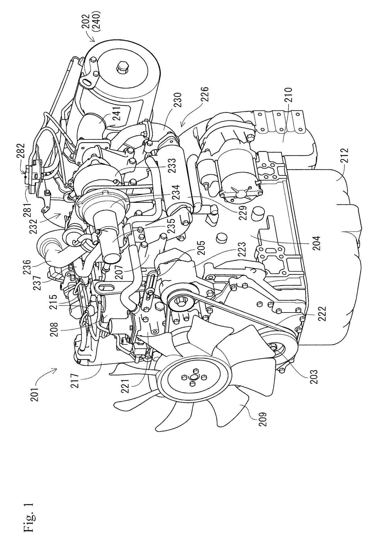
[0043]First, outlines of a common rail engine 201 will be described with reference to FIGS. 1 to 6. In the following description, both sides which are parallel to a crankshaft axis (both sides of crankshaft axis) are called front and rear, a side where a cooling fan 209 is placed is called a right side, a side where a flywheel housing 210 is placed is called a left side, a side where an exhaust manifold 7 is placed is called a front side, and a side where an intake manifold 6 is placed is called a rear side, and they serve as the basis of a positional relation of four directions and upward and downward directions of the engine 201.

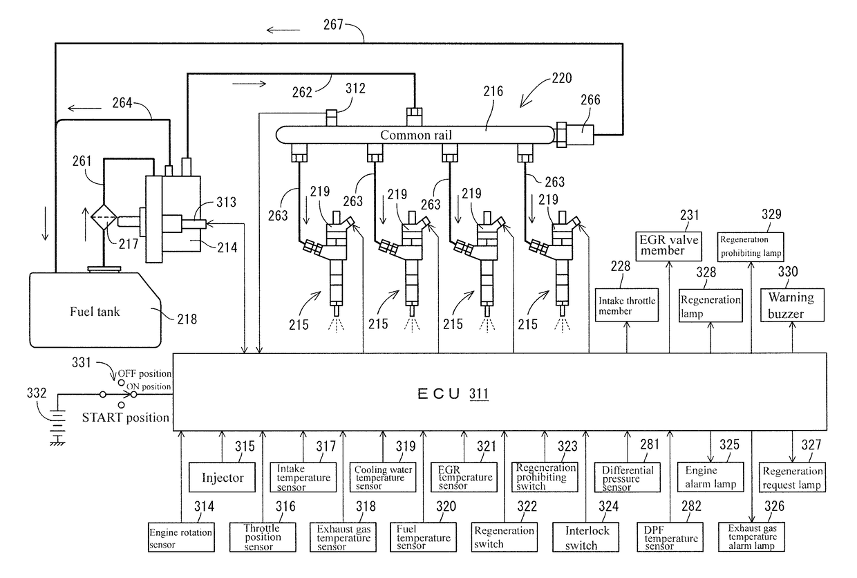
[0044]As shown in FIGS. 1 to 6, the engine 201 as a prime mover provided in an operation machine such as an agricultural machine, a construction machine and an earth-moving machine includes an exhaust ...


PUM


Abstract

It is an object to make it possible to burn and remove particulate matter without generating runaway even if the particulate matter is excessively accumulated at the time of regeneration of an exhaust gas purification device. A common rail engine and the exhaust gas purification device placed in an exhaust gas path of the engine are provided. A plurality of regeneration controls for burning and removing the particulate matter accumulated in the exhaust gas purification device can be executed. The plurality of regeneration controls include at least non-operation regeneration control for raising exhaust gas temperature by combining post injection (E) and predetermined high speed rotation speed, and recovery regeneration control which can be executed when the non-operation regeneration control fails. In the non-operation regeneration control and the recovery regeneration control, the engine is driven exclusively for burning and removing the particulate matter. The recovery regeneration control is carried out at exhaust gas temperature lower than that of the non-operation regeneration control while taking time longer than that of the non-operation regeneration control.

Description

TECHNICAL FIELD[0001]The present invention relates to an exhaust gas purification system for an engine provided in an operation machine such as a construction machine, an agricultural machine and an engine power generator.BACKGROUND ART OF THE INVENTION[0002]As countermeasures against exhaust gas of a diesel engine (simply engine, hereinafter), there is such a well-known conventional technique that particulate matter (PM) and the like in exhaust gas are collected by providing an exhaust gas filter (diesel particulate filter) in an exhaust gas path of an engine, and exhaust gas is restrained from being discharged into atmosphere (see Patent Documents 1 and 2 for example). If PM collected by the exhaust gas filter exceeds a prescribed amount, flowing resistance in the exhaust gas filter is increased and engine output is lowered. Therefore, PM accumulated on the exhaust gas filter is removed by raising temperature of exhaust gas, thereby restoring (regenerating) PM collecting ability o...

Claims


Application Information

Patent Timeline
IPC IPC(8): F01N3/025F01N3/023F02D41/38F02D41/02F02D41/40F01N9/00F01N13/00F01N3/035F01N3/22F01N3/32
CPCF01N9/002F01N3/0253F02D41/029F02D41/0245F02D41/3809F02D41/405F01N3/0232Y02T10/44F01N3/035F01N3/225F01N3/323F01N13/0097F01N2430/00F01N2590/08F01N2610/03F01N2900/1602F01N2900/1606F02D2200/101Y02T10/26Y02T10/12Y02T10/40
Inventor SHIOMI, HIDEOFUKUDA, TOMOHIROOHTA, ATSUSHI
Owner YANMAR POWER TECHNOLOGY CO LTD
Why Eureka
Try Eureka