
Time-of-flight analyzer

Inactive Publication Date: 2006-01-26
SHIMADZU CORP
View PDF2 Cites 16 Cited by
  • Summary
  • Abstract
  • Description
  • Claims
  • Application Information

AI Technical Summary

Benefits of technology

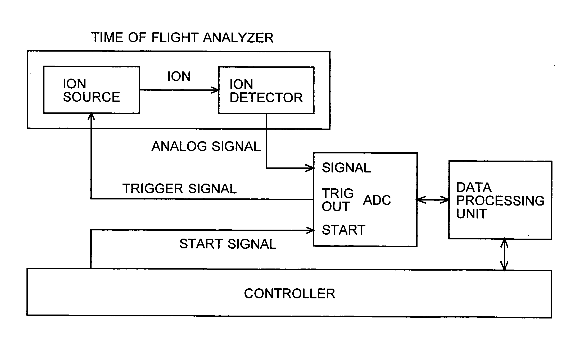
[0023] In view of the above-described problems, an object of the present invention is to provide a time-of-flight analyzer in which the timings of the ion generation and start sampling in the ion signal recorder are adequately adjusted, and the center of a peak is determined at high accuracy with fewer measurements.
[0030] The start signal given externally from the controller and the analog to digital conversion of the signal are not synchronized. But the analog to digital conversion and the trigger signal to the ion source are both synchronized with the internal clock because signals are processed in synchronism with the internal clock. So, the timing to start acceleration of ions in the ion source and the timing to start sampling and recording of the ion signal are synchronized. This alleviates the above-described problem of the conventional time-of-flight analyzer by eliminating a timing error of one clock cycle at most.
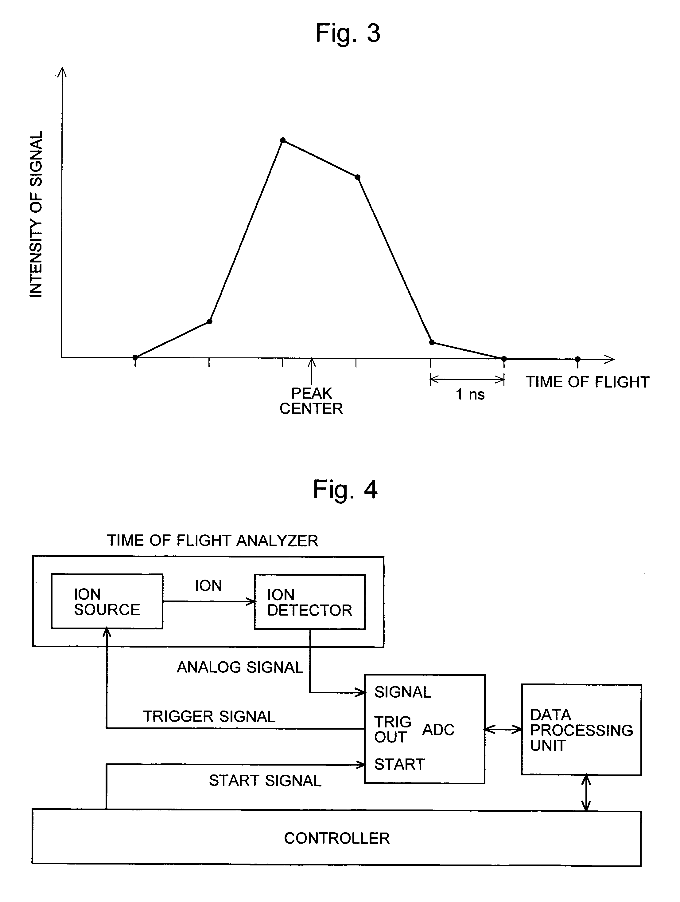
[0031] Thus, according to the time-of-flight analyzer of the present invention, the trigger signal for representing a start of data sampling in the ion signal recorder is generated in synchronism with the internal clock of the ion signal recorder, and the trigger signal is used to start acceleration of ions in the ion source. This suppresses a timing error in the conventional time-of-flight analyzer originating from asynchronous ion generation and sampling. Since the deviation of the central position of a peak in a mass spectrum becomes rather small, the mass to charge ratio of an ion can be determined at high accuracy with fewer measurements. This is especially advantageous in the case where a composition of the sample is such as in the case of an LC-MS. The molecular structure of each component of the sample can be determined within a rather short period while the component is introduced into the ion source.

Problems solved by technology

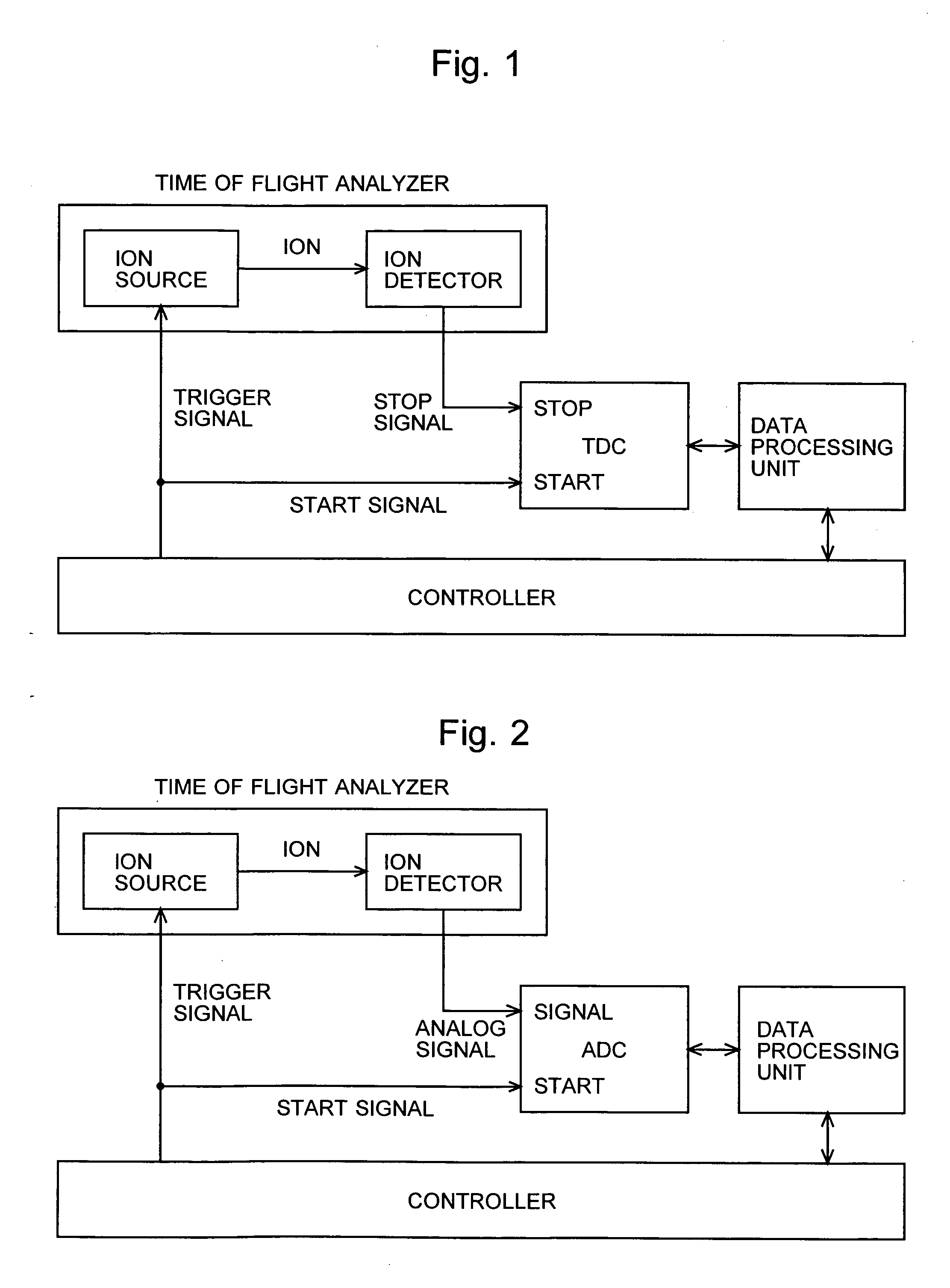
Since, as described above, in conventional TOF mass spectrometers, the timing of start acceleration of ions in the ion source and the clock of the ion signal recorder are not synchronized, the timing to start data sampling includes a timing error of one clock cycle at most.
Especially in the case of fewer measurements, it is the major cause of deteriorating the accuracy of the center of a peak or peaks.

Method used


Image

  • Time-of-flight analyzer
  • Time-of-flight analyzer
  • Time-of-flight analyzer

Examples


Embodiment Construction

[0039] A high performance liquid chromatograph ion trap time-of-flight mass spectrometer (LC-IT-TOFMS) embodying the present invention is described. FIG. 5 is a schematic diagram of the main part of the LC-IT-TOFMS.

[0040] The high performance liquid chromatograph (LC) 1 is an analyzer where a liquid sample is injected, and its components are ejected at different timings according to their properties. In the LC-IT-TOFMS of the present embodiment, the LC 1 is used as a preparatory device of the mass spectrometer. The components of the liquid sample ejected from the LC 1 in time-series are ionized in an ion introduction optics 2, and the ions are injected into the vacuum space. The ion introduction optics 2 includes an ionizing probe and an ion guide. Ionizing probes such as an electrospray ionizing probe or an atmospheric pressure chemical ionizing probe are used to ionize the component, wherein the liquid component is broken into tiny droplets, the droplets are then dried, and are g...


PUM


Abstract

In order to provide a time of flight analyzer in which the timings of the ion generation and the ion signal recorder are synchronized, and the peak center position can be determined at high accuracy with fewer measurements, the time of flight analyzer of the present invention includes an ion source and an ion signal recorder working on an internal clock, wherein the ion signal recorder generates a trigger signal in synchronism with the internal clock in order to generate ions in the ion source. Since the timing of accelerating ions in the ion source and the timing of digital sampling and recording of the ion signal, which is detected in the ion detector, in the ion signal recorder are synchronized, the timing error occurred in conventional methods can be suppressed.

Description

[0001] The present invention relates to a time-of-flight (TOF) analyzer in which ions are generated in an ion source and the time-of-flight of the ions is measured in an ion detector. The TOF analyzer of the present invention can be used in a Matrix-Assisted Laser Desorption / Ionization (MALDI) type TOF mass spectrometer, or in an ion trap type TOF mass spectrometer in which an ion trap is used as the ion source. BACKGROUND OF THE INVENTION [0002] In a TOF mass spectrometers, ions are generated in an ion source, that is, the ions are accelerated to a predetermined speed and ejected to a flight space, and the ions are detected by an ion detector after flying in the flight space of a certain length. The time-of-flight, i.e. the length of time from the time point when the ions are ejected from the ion source to the time point when the ions are detected by the ion detector, is recorded by an ion signal recorder, and the mass to charge ratios of the ions are determined using the recorded ...

Claims


Application Information

Patent Timeline
IPC IPC(8): H01J49/40
CPCH01J49/40
Inventor KAWATO, EIZO
Owner SHIMADZU CORP
Learn More