Motor stator having transposed winding layers

Active Publication Date: 2006-01-26
BLUWAV SYST LLC
View PDF7 Cites 21 Cited by
  • Summary
  • Abstract
  • Description
  • Claims
  • Application Information

AI Technical Summary

Benefits of technology

[0006] The present invention fulfills the above described needs, at least in part, by successively forming a plurality of individual layers of wire strands on each stator pole of a pole pair. Rather than the prior art techniques of winding a single thick wire or a number of bundled wires on a stator, the present invention forms a number of winding layers, each winding layer fabricated of the same relatively thin wire gauge. The winding layers are formed individually on each pole of a pole pair. A first layer is applied directly on a pole and each successive layer is assembled on top of the last previous layer. Each layer of one pole of the pole pair is connected in series with a layer of the other pole of the pole pair to obtain a number of individual series coil connections equal in number to the number of layers. As ind

Problems solved by technology

Electric traction systems demand high torque from low voltage propulsion units.
The use of a thick single wire to form a stator winding typically introduces unacceptable high frequency skin effect losses.
As one spool of wire is required for each strand, a winding system that must accommod

Method used


Image

  • Motor stator having transposed winding layers
  • Motor stator having transposed winding layers
  • Motor stator having transposed winding layers

Examples


Example

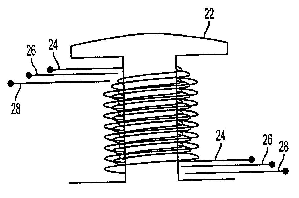
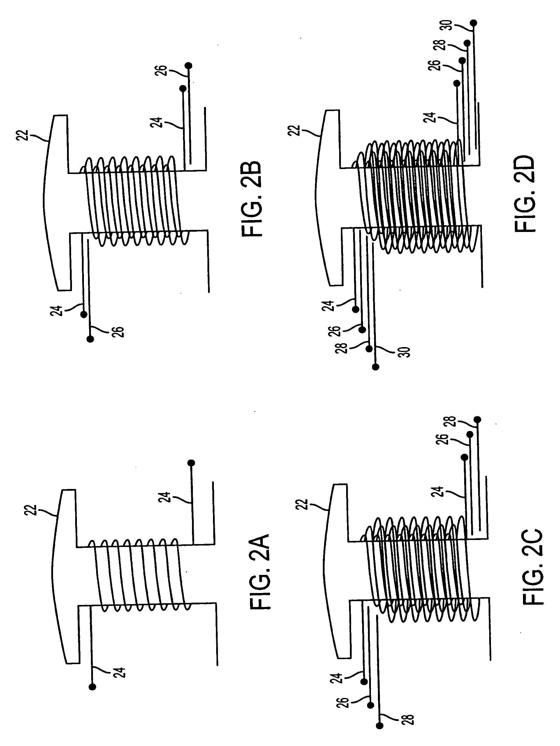
[0013]FIGS. 2a-2d depict the formation of four winding layers on a stator pole 22 of a pole pair segment. The selection of four layers is merely representative of the invention as the number of layers can be adjusted in dependence upon various factors, including current load requirements, specific wire gauge, number of coil turns, and pole configuration. In FIG. 2a, a winding layer 24 is formed on pole 22. The wire from which the winding is formed is of relatively low wire gauge and supplied from a wire spool, not shown. A relatively low tension coil-winding machine of conventional design can be utilized as bending of the wire is not difficult. In FIG. 2b, a second winding layer 26 is formed over the first winding 24. Wire from the same spool is used by the same winding machine. As a single strand of the same wire source is used to form both layers, a high slot fill factor can be achieved. In similar fashion, winding layers 28 and 30 are formed over the preceding layers, as illustra...


PUM

PropertyMeasurementUnit
Electrical inductanceaaaaaaaaaa

Abstract

An electric motor is provided with a multi-layered winding stator core configuration. A plurality of individual layers of wire strands are successively formed on each stator pole of a pole pair. Each winding layer is fabricated of the same relatively thin wire gauge. A first layer is applied directly on a pole and each successive layer is assembled on top of the last previous layer. Each layer of one pole of the pole pair is connected in series with a layer of the other pole of the pole pair to obtain a number of individual series coil connections equal in number to the number of layers. As inductance and resistance characteristics of the layers differ from each other as the layers increase in distance from each pole, layers from one pole of the pole pair are connected to respective layers different in order from that of the other pole pair.

Description

FIELD OF THE INVENTION [0001] The present invention relates to motor stators and, more particularly, to a multi-layered winding configuration of a stator core pole pair and a technique for forming and connecting the winding layers. BACKGROUND ART [0002] Development of efficient electric motor drives for vehicles, with improved electronic control systems and portable power sources, has drawn increasing attention as a viable alternative or adjunct to combustion engine drives. For example, U.S. Pat. No. 6,492,756 to Maslov et al. and U.S. Pat. No. 6,617,746 to Maslov et al., both commonly assigned with the present invention, describe motor structures that provide high torque output capability with minimum power consumption that are especially suitable to electric vehicle propulsion. Electromagnets are used as isolated magnetically permeable structures configured in a stator annular ring. Isolation of the electromagnet groups permits individual concentration of flux in the magnetic core...

Claims


Application Information

Patent Timeline
IPC IPC(8): H02K1/00H02K17/00H01F7/06
CPCH02K3/18Y10T29/49071Y10T29/49073H02K3/28
Inventor RAHMAN, ZIAUR
Owner BLUWAV SYST LLC
Why Eureka
Try Eureka