Liquid circulation system and liquid cooling system therewith

a circulation system and liquid cooling technology, applied in the direction of positive displacement liquid engines, piston pumps, liquid fuel engines, etc., can solve the problems of small impellers that cannot increase flow rates, lose the general versatility of pumps themselves, and reduce the flow rate of coolant. , to achieve the effect of reducing the loss of pressure drop in piping

Inactive Publication Date: 2006-01-26
HITACHI LTD
View PDF10 Cites 19 Cited by
  • Summary
  • Abstract
  • Description
  • Claims
  • Application Information

AI Technical Summary

Benefits of technology

[0016] Accordingly, the present invention can miniaturize a liquid circulation system and minimize pressure drop loss in piping.

Problems solved by technology

The foregoing related art disclosed in JP-A-2004-92610 has a problem that a small-sized impeller cannot increase a flow rate because efficiency is lower than that of a large-sized impeller.
The related art using a small-diameter port has a problem that the flow rate of coolant becomes lower, especially in using coolant with high viscosity.
Moreover, the art disclosed in JP-A-2004-47921 has a problem that the shape of a pump case must be specialized in accordance with the shape of an object to be cooled because part of a pump casing becomes a heat receiving surface, which leads to lost general versatility of a pump itself and difficult cost reduction by mass-production effect.
One of fundamental problems of the centrifugal pumps is that a liquid flow stops when air is mixed into an internal pump.
A conventional liquid cooling system aimed at free maintenance has a problem of the permeability of coolant from a pump surface, namely, that coolant is lost while passing through a material constituting a pump case.
However, if an impeller must be driven by magnetic force, metal cannot be, in practice, used for the case and polymer material is unavoidably used.
A portion which is hardly associated with the magnetic force can use metal, which causes a problem that a cost increase occurs.

Method used


Image

  • Liquid circulation system and liquid cooling system therewith
  • Liquid circulation system and liquid cooling system therewith
  • Liquid circulation system and liquid cooling system therewith

Examples


first embodiment

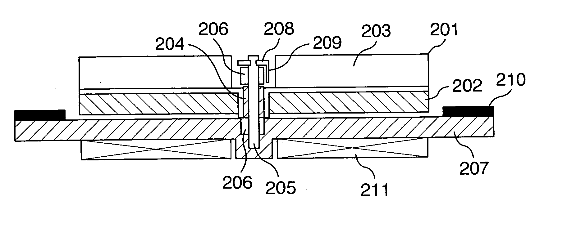
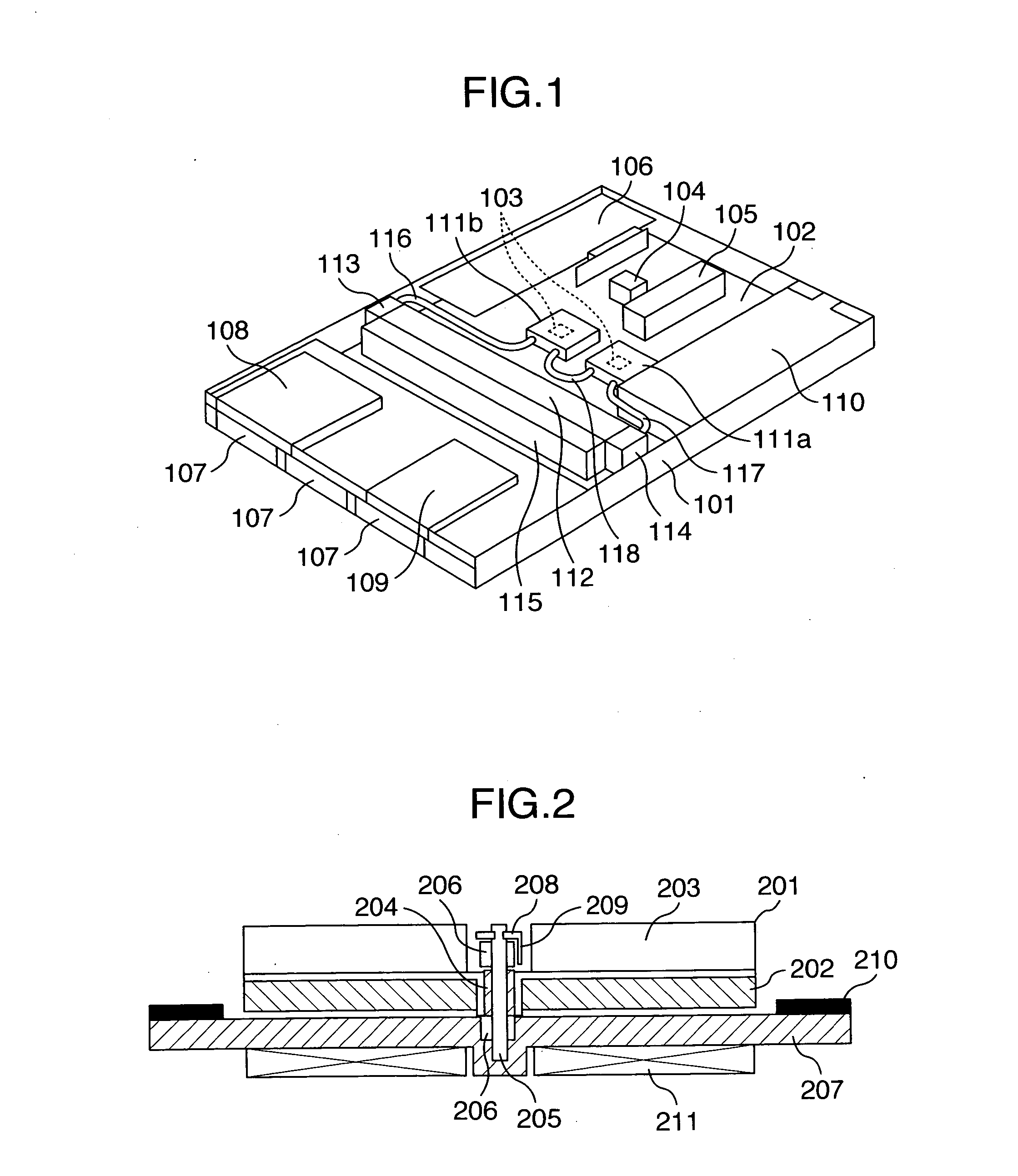
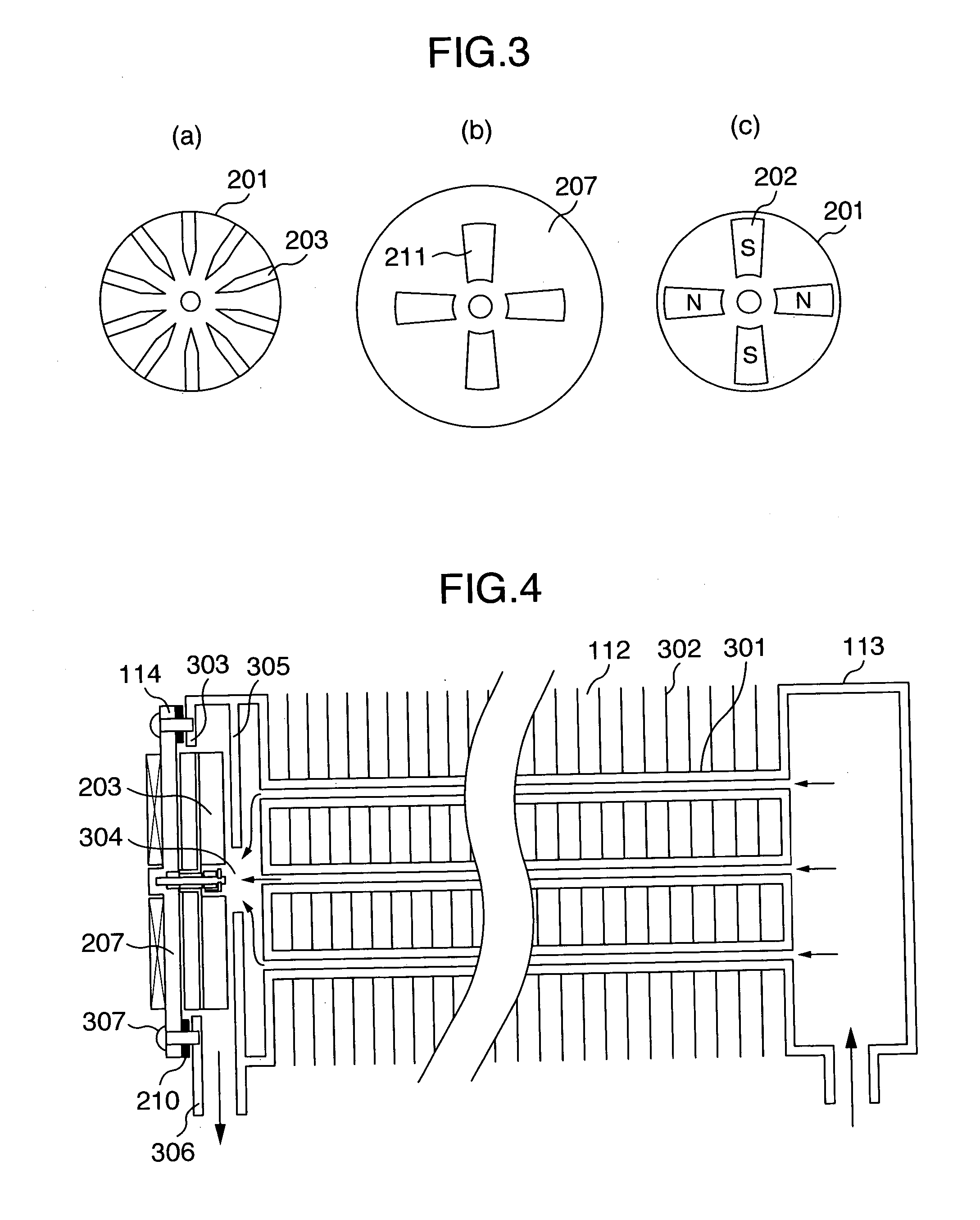
[0026]FIG. 1 is a perspective view illustrating an example of a configuration of an electronic device to which a liquid cooling system is applied according to an embodiment of the present invention, where a reference symbol 101 is a casing, a reference symbol 102 is a mother board, a reference symbol 103 is a CPU, a reference symbol 104 is a chip set, a reference symbol 105 is a memory, a reference symbol 106 is a PCI board, a reference symbol 107 is a HDD, a reference symbol 108 is a CD-ROM, a reference symbol 109 is FDD, a reference symbol 110 is a power supply unit, reference symbols 111a, 111b are jackets, a reference symbol 112 is a radiator, a reference symbol 113 is a tank section, a reference symbol 114 is a pump section, a reference symbol 115 is a fan, and reference symbols 116 to 118 are tubes. The electronic device illustrated in FIG. 1 is an approx. 44.4 high slim server, that is, a 1U server as an example.

[0027] The server as the electronic device illustrated in FIG. ...

second embodiment

[0047]FIG. 5 is a sectional view illustrating a configuration of a liquid cooling system according to a second embodiment. Referring now to FIG. 5, the liquid cooling system according to this embodiment is described below. The liquid cooling system illustrated in FIG. 5 is constructed by installing a pump section on an independent tank section. In FIG. 5, a reference symbol 401 is a tank, reference symbols 402, 403 are ports, a reference symbol 404 is a wall surface, a reference symbol 405 is a hole, and a reference symbol 406 is a partition plate. Other symbols are the same as in FIGS. 1 to 4. An arrow indicated in FIG. 5 shows a flow of coolant.

[0048] In FIG. 5, the tank 401 is made of metal, the bottom surface of the tank 401 has the holed wall surface 404 for mounting the pump section 114 thereon, where the pump section 114 is assembled. The vanes 203 of the pump section 114 are positioned inside the wall surface 404. The pump section 114 is fixed on the wall surface 404 by the...

third embodiment

[0057]FIG. 6 is a sectional view illustrating a configuration of a liquid cooling system according to a third embodiment. Referring to the drawing, a liquid cooling system according to this embodiment is described. The liquid cooling system illustrated in FIG. 6 is constituted by integrating the pump section with a radiator. In FIG. 6, a reference symbol 501 is a jacket, reference symbols 502, 503 are ports, a reference symbol 504 is a wall surface, a reference symbol 505 is a hole, a reference symbol 506 is a duct, a reference symbol 507 is an opening section, and a reference symbol 508 is a heat sink. Other symbols are the same as in FIGS. 1 and 2. An arrow indicated in FIG. 6 shows a flow of coolant.

[0058] In FIG. 6, the jacket 501 is formed out of metal with excellent thermal conductivity, such as copper or aluminum. Onto the bottom surface of the jacket 501, a heat generating body to be cooled such as a CPU is jointed through thermal conductivity grease or the like. On the sid...


PUM


Abstract

A pump equipped with an impeller having a plurality of vanes is installed through a packing at an opening section formed on a wall surface of one of components in a liquid circulation passage, such as a radiator so that the impeller of the pump section may be disposed herein. Inside the component, there is provided a partition plate formed with a hole at such a position as to face the center of the impeller. A port is provided between a wall surface having the opening section and the partition plate. By the rotation of the impeller, a liquid flow is produced toward the port from the inside of the compartment through the hole.

Description

INCORPORATION BY REFERENCE [0001] The present application claims priority from Japanese application JP2004-214574 filed on Jul. 22, 2004, the content of which is hereby incorporated by reference into this application. BACKGROUND OF THE INVENTION [0002] The invention relates to a liquid circulation system for circulating liquid using a pump and a liquid cooling system therewith, and more particularly to a liquid circulation system equipped with a pump capable of being miniaturized and a mounting structure thereof, and a liquid cooling system therewith. PRIOR ART [0003] The increasing speed of a device and an integrated circuit used in a personal computer, a server or the like, especially a CPU has been recently much-needed, which has been increasing heating value. [0004] The present mainstream of cooling a CPU is a direct air-cooling system for spraying cooling air to a heat sink by fixing the heat sink on the CPU and mounting a fan on it. However, cooling by means of the direct air-...

Claims


Application Information

Patent Timeline
Patent Type & Authority Applications(United States)
IPC IPC(8): F04B35/04F04B17/00
CPCF04B53/08F04D29/588H01L23/473H01L2924/0002H01L2924/00
Inventor OIKAWA, HIRONORI
Owner HITACHI LTD
Why Eureka
Try Eureka