
Flow control in an intravenous fluid delivery system

a fluid delivery system and flow control technology, applied in the field of flow control in the intravenous fluid delivery system, can solve the problems of low power consumption of the present system, and achieve the effects of low power consumption, high electrical isolation, and acceptable leakage currents

Inactive Publication Date: 2006-01-26
VITAL SIGNS INC
View PDF22 Cites 42 Cited by
  • Summary
  • Abstract
  • Description
  • Claims
  • Application Information

AI Technical Summary

Benefits of technology

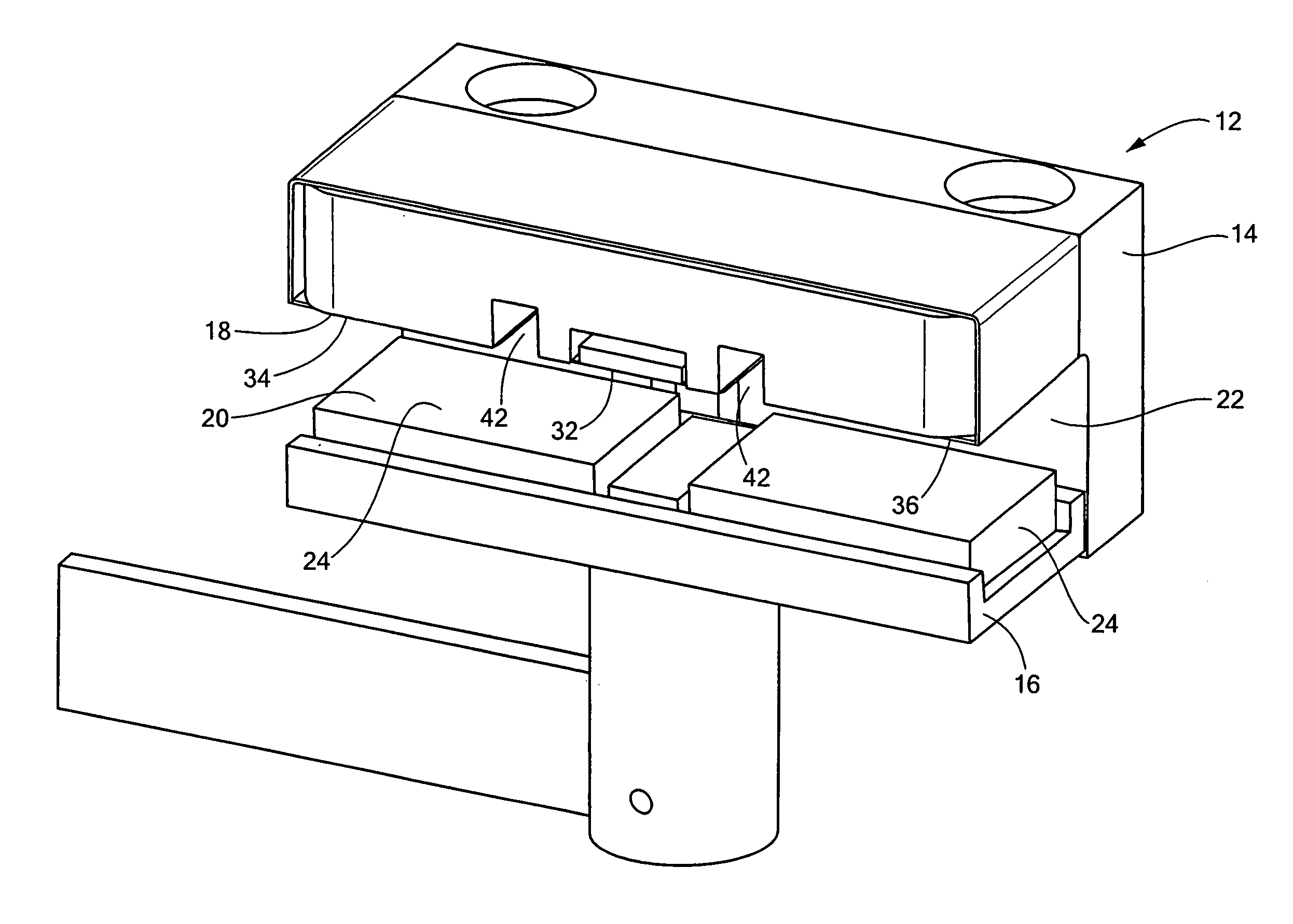
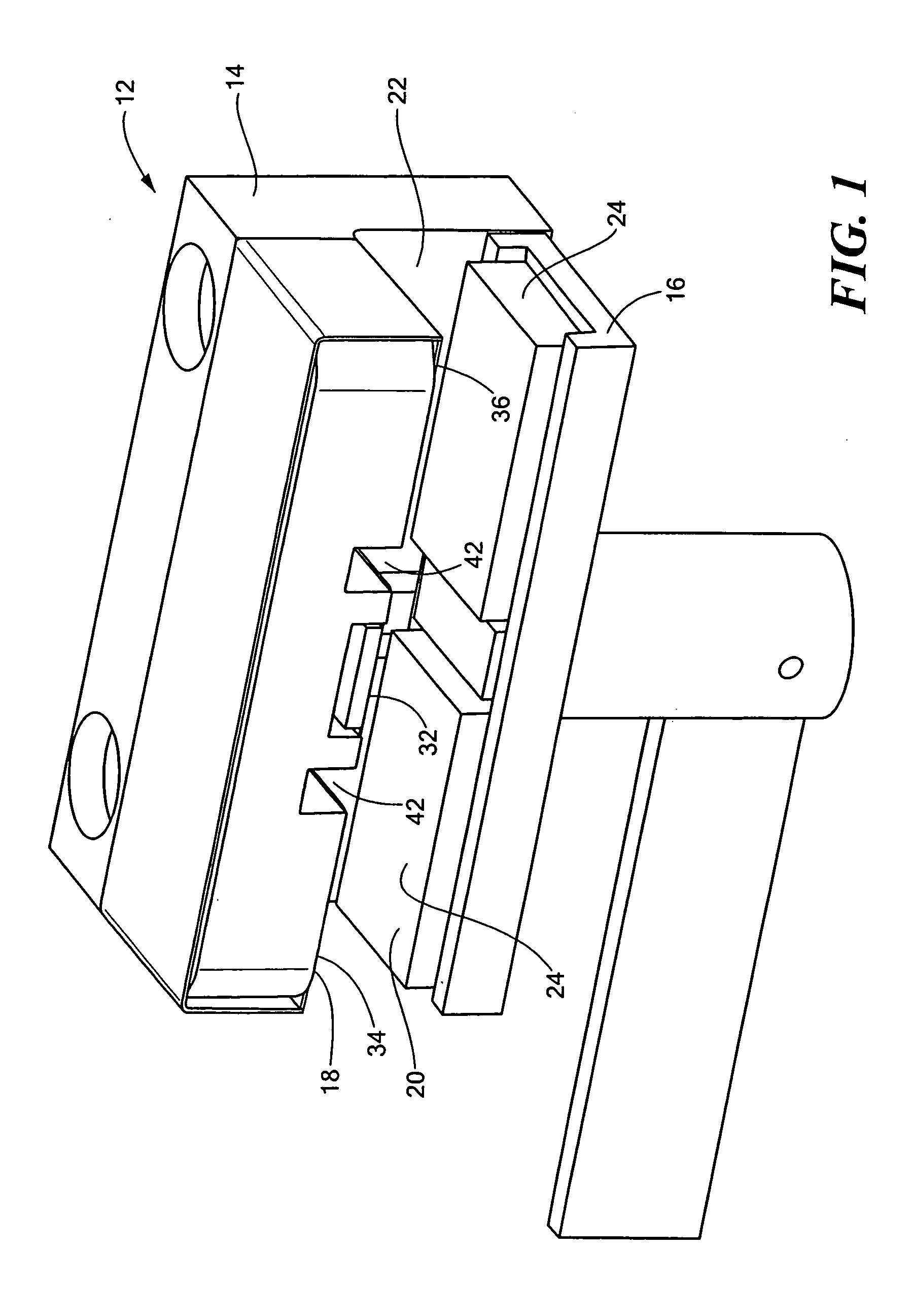
[0015] In one aspect of the present invention, an air or gas bubble detection system is provided that detects the presence or absence of liquid in intravenous (IV) tubing. By detecting the presence of liquid rather than gas, false alarms due to micro bubbles or small air gaps between the sensor and the tubing are avoided. This system is independent of fluid type. Additionally, high electrical isolation is maintained and leakage currents are acceptably low. Also, power consumption is low with the present system.
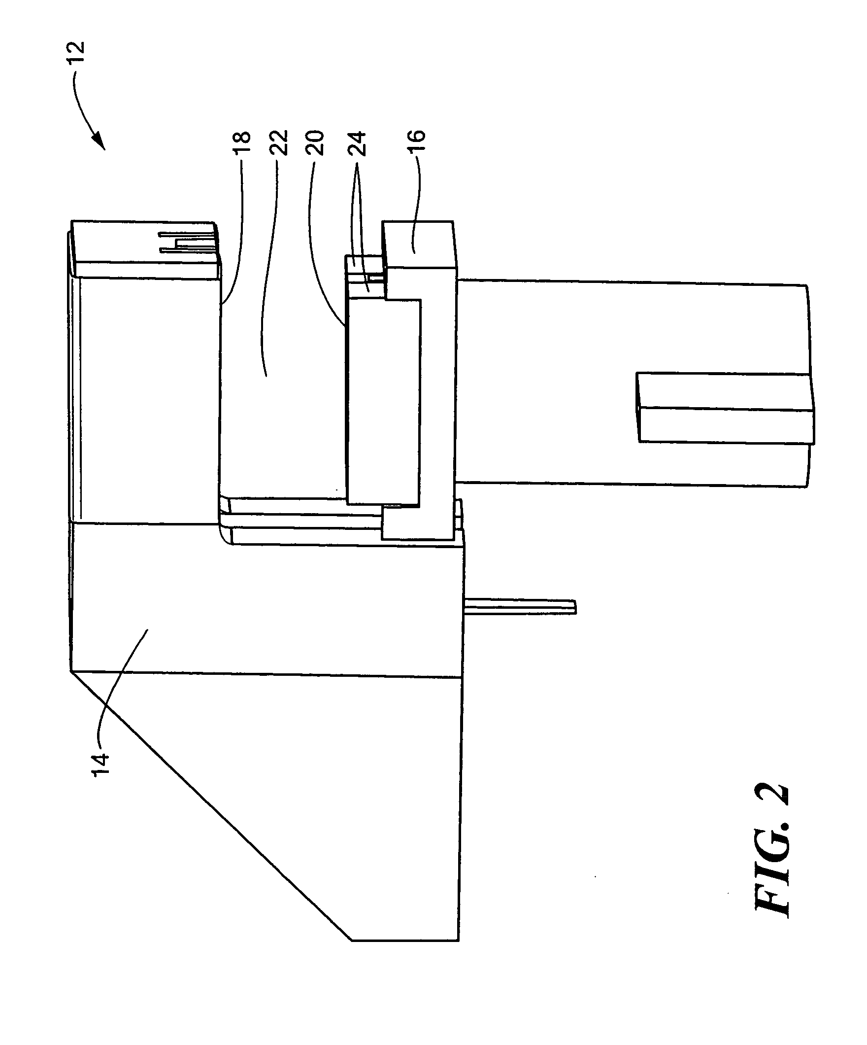
[0016] More particularly, the air or gas bubble detection system employs a circuit that transfers a charge to a sense electrode adjacent the IV tubing and to a reference capacitor. Two grounded electrodes are spaced on the sides of the sense electrode. The three electrodes are aligned parallel with the length of the IV tubing. The tubing and any fluid (liquid or gas) therein act as dielectrics. A grounded shield electrode shapes the electric field toward the tubing and prevents outside fields from interfering with the sensing process. The circuit detects the amount of charge transferred to the reference capacitor, which is indicative of the type of material present. The presence of a liquid produces a high number, whereas the absence of a liquid produces a low number. By comparing the produced number with a limit, the controller determines if an alarm condition is met.

Problems solved by technology

Also, power consumption is low with the present system.

Method used


Image

  • Flow control in an intravenous fluid delivery system
  • Flow control in an intravenous fluid delivery system
  • Flow control in an intravenous fluid delivery system

Examples


Embodiment Construction

Gas Bubble Detection System

[0040] The present invention relates in one aspect to an air or gas bubble detection system for use with an intravenous (IV) fluid infusion system. The system of the present invention detects the presence or absence of liquid in the IV tubing, not the presence of gas. If the system detects that liquid is not present, then gas must be present in the tubing. With this system, false alarms due to detection of micro bubbles or small air gaps between the sensor and the tubing are avoided.

[0041] More particularly, all materials have a physical dielectric constant. Gasses have a very low dielectric constant, plastics have a medium dielectric constant, and liquids have a very high dielectric constant. The present system utilizes electrodes to act as capacitor plates and the adjacent materials (the tubing and any fluid therein) as dielectrics. The detected charge on a reference capacitor is indicative of the type of material present.

[0042] Referring to FIGS. 1-...


PUM


Abstract

An intravenous flow control system provides closed loop control to maintain a desired flow rate. The actual flow rate is determined by two techniques, a geometrically based technique that uses geometric parameters of the IV system, and a thermally based technique that uses the power input to an IV fluid warmer and the temperature of the IV fluid entering and exiting the warmer.

Description

CROSS REFERENCE TO RELATED APPLICATIONS [0001] This application claims the benefit under 35 U.S.C. § 119(e) of U.S. Provisional Patent Application No. 60 / 575,246, filed May 28, 2004, and U.S. Provisional Patent Application No. 60 / 576,258, filed Jun. 2, 2004, the disclosures of both of which are incorporated by reference herein. [0002] This application is related to commonly owned U.S. patent applications entitled Gas Detection in an Intravenous Fluid Delivery System, filed concurrently herewith, and Gas Removal in an Intravenous Fluid Delivery System, filed concurrently herewith.STATEMENT REGARDING FEDERALLY SPONSORED RESEARCH OR DEVELOPMENT [0003] N / A BACKGROUND OF THE INVENTION [0004] Devices to deliver fluids intravenously to a patient involve a number of considerations, such as air or gas bubble detection, gas removal, and flow rate control. [0005] Air and bubble detection in medical intravenous (IV) fluid delivery systems is important. Large amounts of air can cause air embolis...

Claims


Application Information

Patent Timeline
IPC IPC(8): A61M31/00A61M5/14A61M5/168A61M5/36A61M5/38A61M5/40A61M5/44
CPCA61M5/1411A61M5/16813A61M5/36A61M2205/3386A61M5/40A61M5/44A61M2205/3317A61M5/385
Inventor CASSIDY, DAVID E.MAY, ERICBUCCHIANERI, RICHARD
Owner VITAL SIGNS INC
Learn More