Heat treatment apparatus

a heat treatment apparatus and heat treatment technology, applied in lighting and heating apparatus, furnaces, muffle furnaces, etc., can solve the problems of large thermal capacity of conventional thermal processing units, inability to quickly heat and cool, and difficulty in uniform heating of reaction tubes having the above structur

Active Publication Date: 2006-02-02
TOKYO ELECTRON LTD
View PDF9 Cites 29 Cited by
  • Summary
  • Abstract
  • Description
  • Claims
  • Application Information

AI Technical Summary

Benefits of technology

[0052] In addition, it is preferable that the gas-discharging-unit connecting portion is bent. Thus, effect of radiation heat from the reaction tube to ...

Problems solved by technology

However, in the conventional thermal processing unit, since the reaction tube has the double-tube structure, the thermal capacity thereof is large.
Thus, the conventional thermal processing unit is not suitable for rapid heating and rapid cooling.
In addition, it is difficult to uniformly heat the reaction tube having the above structure.
In addition, if the reaction gas introduced into the reaction tube doesn't react but reaches...

Method used


Image

  • Heat treatment apparatus
  • Heat treatment apparatus
  • Heat treatment apparatus

Examples


first embodiment

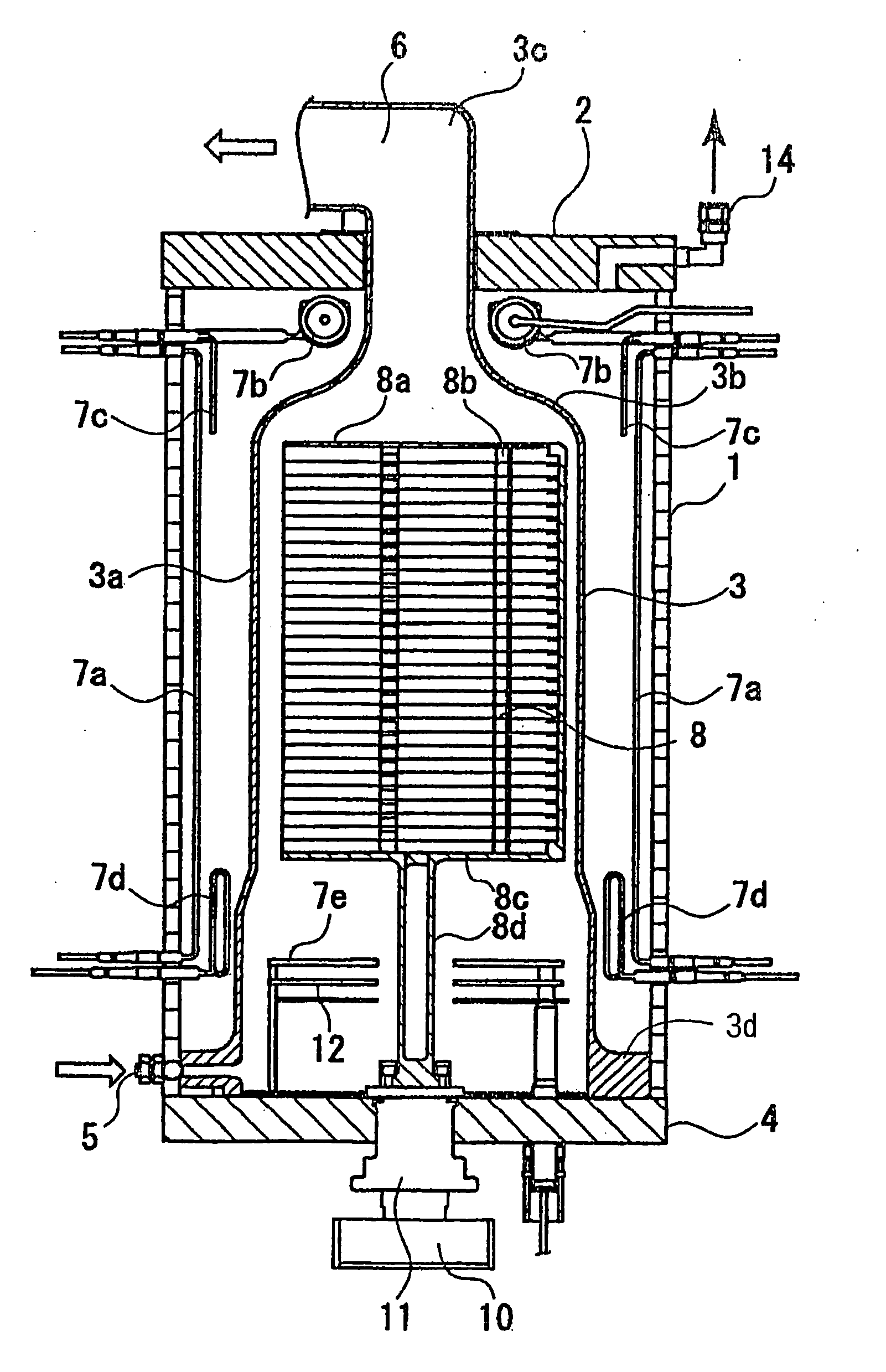
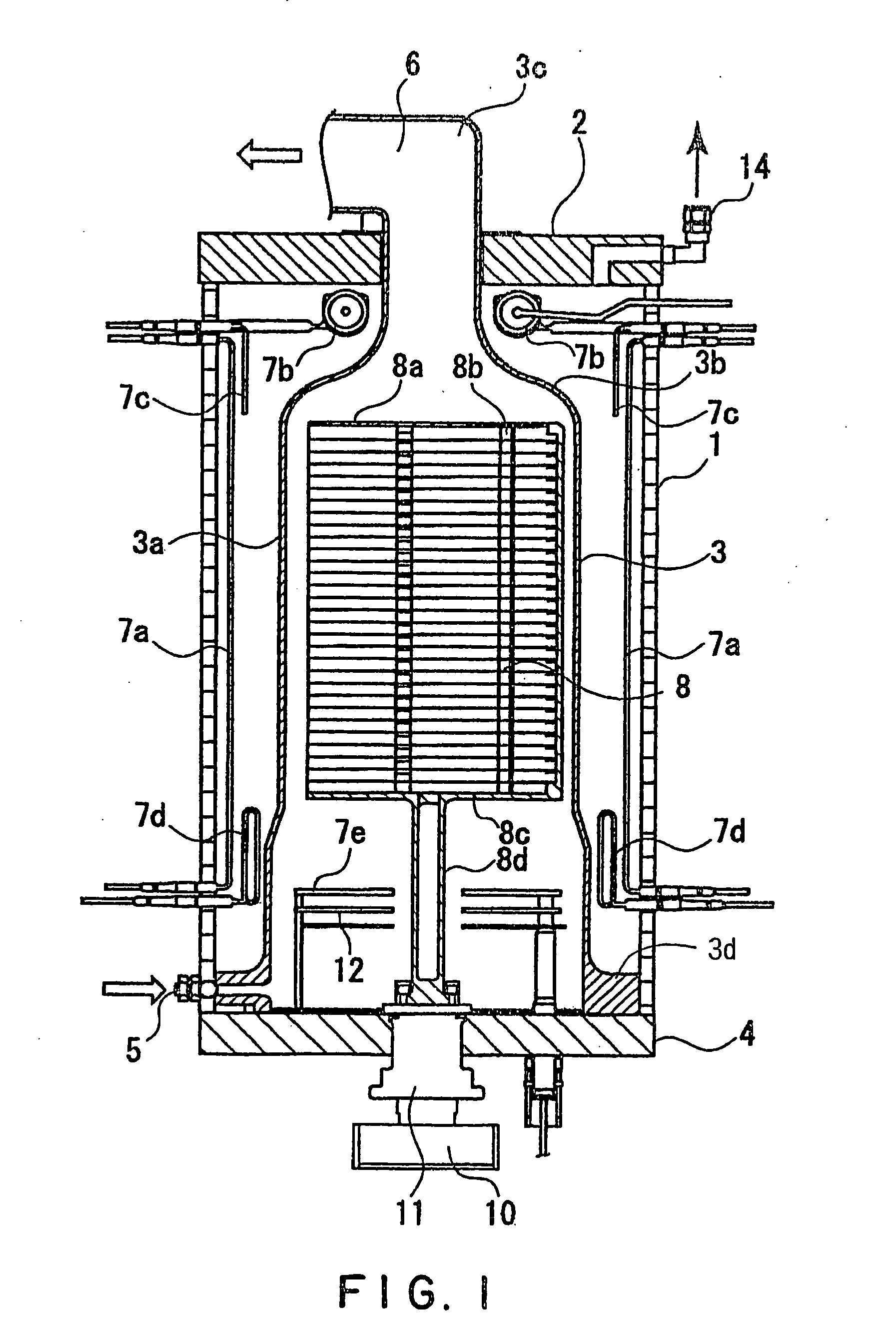
[0064]FIG. 1 is a schematic sectional view showing a thermal processing unit according to a first embodiment of the present invention. The thermal processing unit of the embodiment comprises: a heating-furnace body 1 whose upper end is open; a heating-furnace lid 2 arranged at an upper portion of the heating-furnace body; and a reaction tube 3 whose main part is arranged in the heating-furnace body 1. The heating-furnace lid 2 has a hole through which a narrow-diameter portion of the reaction tube extending from an upper portion of the reaction tube 3 can be inserted. A reaction-tube lower lid 4 is provided at a bottom opening part of the reaction tube 3 in order to maintain airtightness in the reaction tube 3. Substrates to be processed W such as silicon wafers are adapted to be held by a substrate-to-be-processed supporting member 8, which is adapted to be arranged in the reaction tube 3. The substrates to be processed W such as silicon wafers are adapted to be heated by a heating...

second embodiment

[0098] In the present embodiment, additionally to the thermal processing unit of the first embodiment, a temperature measuring unit for measuring a thermal process temperature of the substrates to be processed is provided. FIG. 5 schematically shows a thermal processing unit according to the present embodiment. As shown in FIG. 5, in the present embodiment, three temperature measuring units are arranged. In FIG. 5, a component having the same function as in FIG. 1 is represented by the same numeral sign, and the detailed explanation thereof is omitted.

[0099] Hereinafter, the temperature measuring units that are features of the present embodiment are mainly explained.

(First Temperature Measuring Unit)

[0100] The first temperature measuring unit 9a has: a main-shaft portion consisting of a straight hollow tubular member; and a branch portion branched from the main-shaft portion at a middle position thereof in a perpendicular direction thereto. A known temperature measuring device s...

third embodiment

[0109] In the present embodiment, additionally to the thermal processing unit of the first embodiment, a cooling mechanism for forcibly cooling the reaction tube 3 is provided. FIG. 7 schematically shows a thermal processing unit according to the present embodiment. In FIG. 7, a component having the same function as in FIG. 1 is represented by the same numeral sign, and the detailed explanation thereof is omitted.

[0110] Hereinafter, the cooling mechanism that is a feature of the present embodiment is mainly explained.

[0111] As seen in FIG. 7, the cooling mechanism consists of: a cooling-medium supplying port 13 formed at a lower portion of the wall of the heating-furnace body 1; a cooling-medium supplying system having a cooling-medium supplying unit connected to the cooling-medium supplying port 13 and not shown; and a cooling-medium discharging port 14 formed at the heating-furnace lid 2.

[0112] A medium such as cooling air is pressed from the cooling-medium supplying unit into ...


PUM

PropertyMeasurementUnit
Temperatureaaaaaaaaaa

Abstract

The present invention is a thermal processing unit including: a heating-furnace body whose upper end has an opening; a reaction tube consisting of a single tube contained in the heating-furnace body; a gas-discharging-unit connecting portion formed at an upper portion of the reaction tube, the gas-discharging-unit connecting portion having a narrow diameter; a substrate-to-be-processed supporting member for supporting a substrate to be processed, contained in the heating-furnace body; and a heating unit for heating the substrate to be processed supported by the substrate-to-be-processed supporting member. The heating unit has: a first heating portion arranged around the reaction tube, a second heating portion arranged around the gas-discharging-unit connecting portion, a third heating portion arranged around an upper portion of the reaction tube, a fourth heating portion arranged around a lower portion of the reaction tube, and a fifth heating portion arranged under the substrate-to-be-processed supporting member.

Description

FIELD OF THE INVENTION [0001] The present invention relates to a thermal processing unit that is suitable for a thermal process to an object to be processed such as a semiconductor wafer. DESCRIPTION OF THE RELATED ART [0002] Conventionally, in a semiconductor manufacturing process, there is a step of depositing a thin film or an oxide film onto a surface of a semiconductor wafer as an object to be processed, or a step of conducting a diffusion of impurities onto the surface. For these steps, a thermal processing unit such as a CVD unit, an oxide-film forming unit or a diffusion unit has been used. [0003] In such a thermal processing unit, a plurality of wafers, which are objects to be processed, are placed on an object-to-be-processed holding member called a wafer boat in a vertical arrangement, and then loaded in a reaction tube called a process tube that has been heated to a high temperature. Then, a reaction gas is introduced into the reaction tube, so that a thermal process to ...

Claims


Application Information

Patent Timeline
IPC IPC(8): C23C16/00H01L21/00H01L21/205H01L21/22
CPCH01L21/67109H01L21/22
Inventor SAITO, TAKANORIYAMAGA, KENICHINAKAO, KEN
Owner TOKYO ELECTRON LTD
Why Eureka
Try Eureka