
Information reading apparatus and information reading system

a technology of information reading and information reading, which is applied in the direction of burglar alarm mechanical actuation, burglar alarm by hand-portable article removal, instruments, etc., can solve the problems of not being popularized and users being unable to perform the next suitable operation

Inactive Publication Date: 2006-02-02
PANASONIC CORP
View PDF8 Cites 57 Cited by
  • Summary
  • Abstract
  • Description
  • Claims
  • Application Information

AI Technical Summary

Benefits of technology

[0016] Accordingly, it is an object of the present invention to provide an information reading apparatus and an information reading system using the same, which can transmit a data read from a contactless data carrier as well as information on the state of the contactless data carrier located in a communication range and can remarkably reduce investment costs for the card infrastructure.
[0022] By this structure, the information reading apparatus can transmit the information that the plurality of the contactless data carriers exist in the communication range to the outside using the clock signal and the data signal with the communication specification equal to that of the magnetic card reading apparatus, and the upper level apparatus can analyze the information received from the information reading apparatus and allow the notifying part to notify the information if the information is the information that the plurality of the contactless data carriers exist.
[0024] By this structure, the information reading apparatus can transmit the information that the contactless data carrier is not matched to the predetermined specification to the outside using the clock signal and the data signal with the communication specification equal to that of the magnetic card reading apparatus, and the upper level apparatus can analyze the information received from the information reading apparatus and allow the notifying part to notify the information if the information is the information that the contactless data carrier is not matched to the predetermined specification.

Problems solved by technology

However, the system using the contactless smart card is now used in some fields, but is not currently popularized, because large-scale initial investment is required to switch an infrastructure for the magnetic card which has been established up to now, such as existing various terminals or networks, to an infrastructure for the contactless smart card.
Thus, the user cannot be prompted to perform the next suitable operation.

Method used


Image

  • Information reading apparatus and information reading system
  • Information reading apparatus and information reading system
  • Information reading apparatus and information reading system

Examples


first embodiment

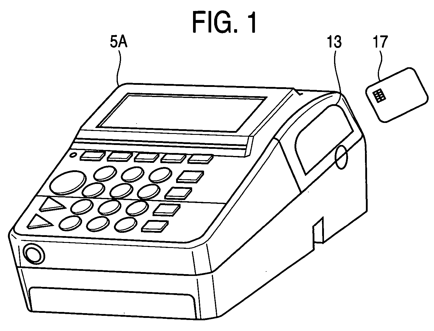
[0044] Hereinafter, a payment terminal apparatus (including an information reading apparatus and an information reading system) according to a first embodiment of the present invention will be described with reference to FIGS. 1 through 7.

[0045]FIG. 1 is a perspective view of a payment terminal apparatus 5A for processing payment using a payment card according to the present embodiment, and illustrates the state that a contactless smart card 17 which is an example of a contactless data carrier is held to an antenna 13 having a reading function.

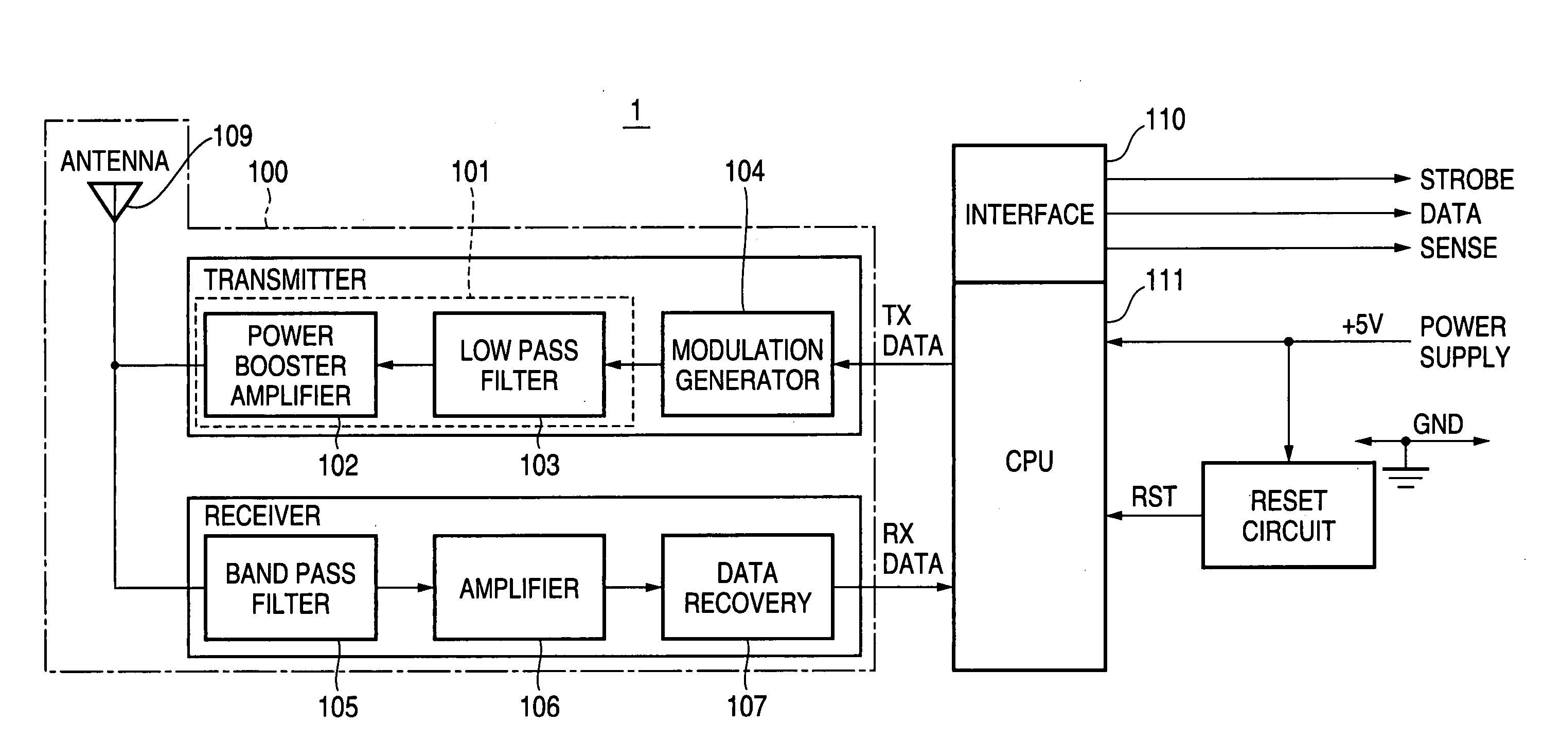
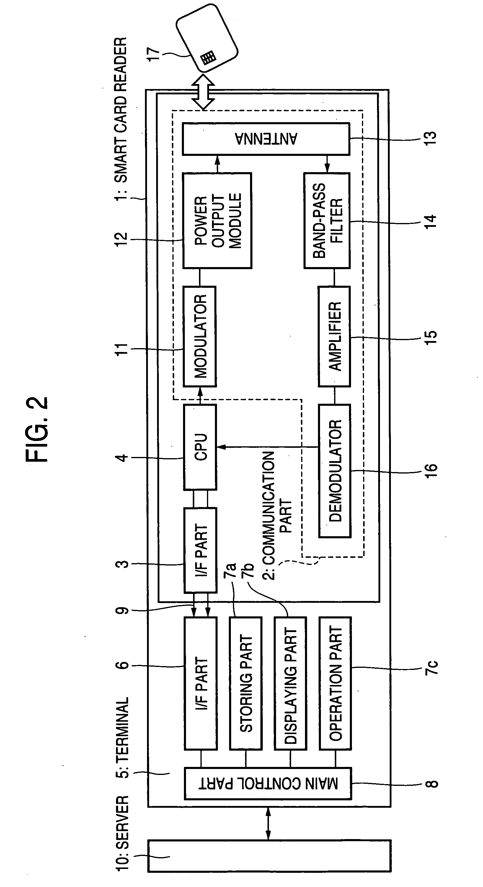
[0046]FIG. 2 is a functional block diagram of the present embodiment. This apparatus is largely divided into a smart card reader 1 part and a terminal 5 part. In the Figure, a reference numeral 1 denotes a smart card reader corresponding to the contactless smart card 17. The smart card reader 1 includes a communication part 2 wirelessly communicating with the contactless smart card 17, an I / F (interface) part 3 for transmitting information r...

second embodiment

[0088]FIG. 13 illustrates a schematic view of a payment terminal apparatus according to a second embodiment of the present invention, and FIG. 14 is a functional block diagram of the payment terminal apparatus 5B.

[0089] In the present embodiment, the same portions as the first embodiment are denoted by the same reference numerals and their description will be omitted. The present embodiment is different from the first embodiment in that a multi-card reader 1M is a complex card reader for processing both the magnetic card 18 and the contactless smart card 17 and an output signal of a card detecting sensor 26 is also output from the I / F part 3 of the multi-card reader 1M to the terminal 5B.

[0090] Furthermore, the I / F part 3 of the multi-card reader 1M also serves as a signal selector for determining whether the information read by the magnetic head 21 is output to the terminal 5B or whether the information based on the information received by the antenna 13 is output to the terminal...


PUM


Abstract

A card system of a magnetic card which reduces investment costs for switching over a card infrastructure and transmits / receives a data of a contactless smart card and information representing the state of the contactless smart card only by changing software is provided. Based on the communication result with the contactless smart card 17 through a communication part 2, the information of the contactless smart card 17 or the information representing the state of the contactless smart card 17 are output with different formats or different timing charts, respectively, and are output through an I / F part 3 with a specification equal to that of an output signal of a magnetic card reader.

Description

[0001] This application is based on Japanese Patent Application No. 2004-221347, which is incorporated herein by reference. BACKGROUND OF THE INVENTION [0002] 1. Field of the Invention [0003] The present invention relates to an information reading apparatus, and more particularly, to an information reading apparatus and an information reading system which can read various information stored in a card. [0004] 2. Description of the Related Art [0005] Recently, a system corresponding to various cards such as a cash card, a credit card or a commutation ticket is switched from a conventional magnetic card to a smart card or a new system corresponding to the smart card has been introduced. Recently, a contactless smart card is attracting much attention. This contactless smart card can send or receive information only by holding the contactless smart card to a reading apparatus and has a rapid processing speed more than that of the magnetic card. Also, since the contactless smart card incl...

Claims


Application Information

Patent Timeline
IPC IPC(8): G06K7/08
CPCG06K7/0008G06K7/0004
Inventor IWAMURA, TAKAHIRO
Owner PANASONIC CORP
Learn More