Conductive paste
Inactive Publication Date: 2006-02-02
SUMITOMO ELECTRIC IND LTD
View PDF10 Cites 37 Cited by
- Summary
- Abstract
- Description
- Claims
- Application Information
AI Technical Summary
Benefits of technology
[0009] It is an object of the present invention to solve these problems by providing a conductive paste exhibiting high conductivity even if the sintering is performed at a low temperature. Another aspect of the present invention is to improve the processability of the paste, such as the formation of a thick film of paste.
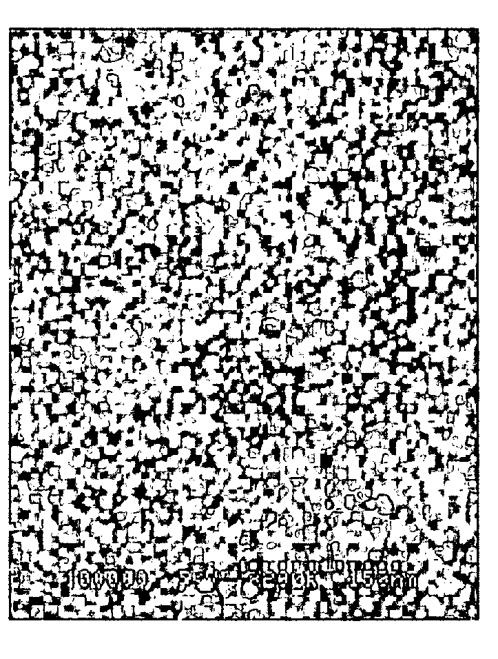
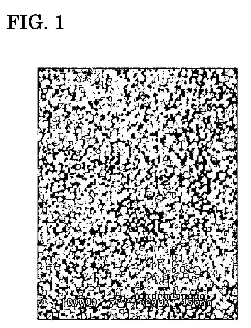
[0010] A conductive paste according to the present invention contains a powdered metal, glass frit, and an organic vehicle as main components. The metal powder is composed of spherical particles (A) having an average primary-particle diameter of 0.1 to 1 μm and spherical particles (B) having an average primary-particle diameter of 50 nm or less. The content of spherical particles (A) ranges from 50 to 99 wt %, and the content of spherical particles (B) ranges from 1 to 50 wt %. Furthermore, the content of the glass frit ranges from 0.1 wt % to 15 wt % to the total amount of the glass frit and the metal powder. In order to achieve high conductivity, preferably fine particles of metal powder are aggregated densely. In the present invention, since gaps among particles (A) having a relatively large particle diameter are filled with particles (B) having a relatively small particle diameter, the packing density of the metal particles is high and the conductivity obtained by sintering at a low temperature is improved.
[0011] In particular, the metal powder preferably includes the spherical particles (A) by 90 to 97 wt % and spherical particles (B) by 3 to 10 wt % so that a high packing density and the effect of low-temperature sintering are sufficiently achieved, and thus the content of expensive spherical particles (B) is reduced, which is economical.
[0014] Glass frit having a large particle diameter compared with that of the metal powder causes a decrease in dispersibility. Glass frit having an average particle diameter of 2 μm or less exhibits improved dispersibility in the paste, and enhances the aforesaid combination effect of metal powders.
[0016] The metal particles in the conductive paste according to the present invention exhibits a high packing density after sintering. This particularly improves the conductivity. The combination of appropriate glass frit and an organic vehicle increases processibility of the conductive paste. The coating applicability of thick film and screen-printing performance are also improved.
Problems solved by technology
Though a thick film must be coated in order to decrease wiring resistance, the thick film increases the residual stress of the film.
When a glass substrate or a dielectric layer-coated glass substrate is used as a base, interference fringes or cracks occur on the glass substrate or in the dielectric layer.
Therefore, it has been difficult to increase the film thickness.
Method used
View moreImage
Smart ImageViewing Examples
Examples
example
[0028] Examples according to the present invention will now be described, but the scope of the present invention is not limited to these examples.
Login to View More PUM
 Abstract
Provided is a conductive paste which can have high conductivity even if the sintering temperature is 500° C. or less, and which does not cause an interference pattern or crack on a substrate even if a thick film thereof is formed on the substrate. The conductive paste comprises main components including a metal powder, a glass frit, and an organic vehicle. The metal powder is composed of spherical particles (A) having an average primary-particle diameter of 0.1 to 1 μm and spherical particles (B) having an average primary-particle diameter of 50 nm or less, and the content of spherical particles (A) ranges from 50 to 99 wt % and the content of spherical particles (B) ranges from 1 to 50 wt %. The content of the glass frit ranges from 0.1 wt % to 15 wt % to the total amount of the glass frit and the metal powder. Preferably, the glass frit does not contain lead and has a working point of 500° C. or less, and the average particle diameter thereof is 2 μm or less. The present invention can widely be applied to print on a substrate and sinter so as to form an electric circuit on the substrate.
Description
TECHNICAL FIELD [0001] The present invention relates to conductive pastes that can widely be used to form electric circuits on insulated substrates by printing and sintering the pastes on the insulated substrates. BACKGROUND ART [0002] Conductive pastes are widely used in electronic components because electrode patterns can be formed by printing them. Nowadays, some of the printed patterns are sintered in order to decrease the electric resistance. Contact resistance between powdered metal particles in the conductive paste decreases due to the progress of sintering and thereby resulting printed patterns exhibit higher conductivity. A method is proposed in which an inorganic material such as glass is also added as a binder to achieve secure binding between the patterns and a substrate, and materials for the method are also proposed. For example, Patent Reference 1 discloses a conductive silver paste (conductive paste) composed of silver powder as a main component, SiO2 powder, glass f...
Claims
Login to View More Application Information
Patent Timeline
 IPC IPC(8): H01B1/12H01B1/00H01B1/22H05K1/09
CPCH05K1/092H01B1/22H01B1/16
Inventor YAMAKAWA, MASAHIROSHIMODA, KOHEJ
Owner SUMITOMO ELECTRIC IND LTD
Features
- R&D
- Intellectual Property
- Life Sciences
- Materials
- Tech Scout
- Unparalleled Data Quality
- Higher Quality Content
- 60% Fewer Hallucinations
Learn More Browse by: Latest US Patents, China's latest patents, Technical Efficacy Thesaurus, Application Domain, Technology Topic, Popular Technical Reports.
© 2025 PatSnap. All rights reserved.Legal|Privacy policy|Modern Slavery Act Transparency Statement|Sitemap|About US| Contact US: help@patsnap.com


