Transient control in optical transmission systems

a transmission system and transient control technology, applied in the field of optical transmission systems, can solve the problems of unacceptably large channel-dependent gain errors and undetected large errors in individual channel gains, and achieve the effects of reducing the transient-induced performance degradation experienced by the surviving channels, good system design, and optimizing performan

Inactive Publication Date: 2006-02-02
LUCENT TECH INC
View PDF14 Cites 4 Cited by
  • Summary
  • Abstract
  • Description
  • Claims
  • Application Information

AI Technical Summary

Benefits of technology

[0011] These transient-control techniques that implement individualized pump adjustments can be further improved by introducing a channel-growth plan that is optimized for transient control, where the transient-control technique can be tuned to provide optimized performance for the limited range of surviving-channel configurations that will likely occur in the system under the applied channel-growth plan.
[0012] Due to typical limitations on the system information available to mitigate transients, transient-control techniques may make several assumptions about the post-transient channel loading. For this reason, some channel configurations that do not satisfy these assumptions will have a poor transient response in terms of the magnitude of impairment on the surviving channels. By introducing a channel-growth plan based upon transient-suppression performance, the transient-induced performance degradation experienced by the surviving channels can be dramatically reduced. A transient-based channel-growth plan can be constructed with good systems design to overlap with lowest-cost and / or best steady-state performance growth plans. Furthermore, by constraining the possible configurations of surviving channels, transient control can be simplified, which leads to both better performance and lower cost.

Problems solved by technology

However, since several nonlinear effects are present within the Raman amplifier, a uniform adjustment to all of the Raman pumps will often result in unacceptably large channel-dependent gain errors.
It is possible to obtain the correct total power gain, yet have undesirably large errors in the individual channel gains.

Method used


Image

  • Transient control in optical transmission systems
  • Transient control in optical transmission systems
  • Transient control in optical transmission systems

Examples


Embodiment Construction

Transient Control

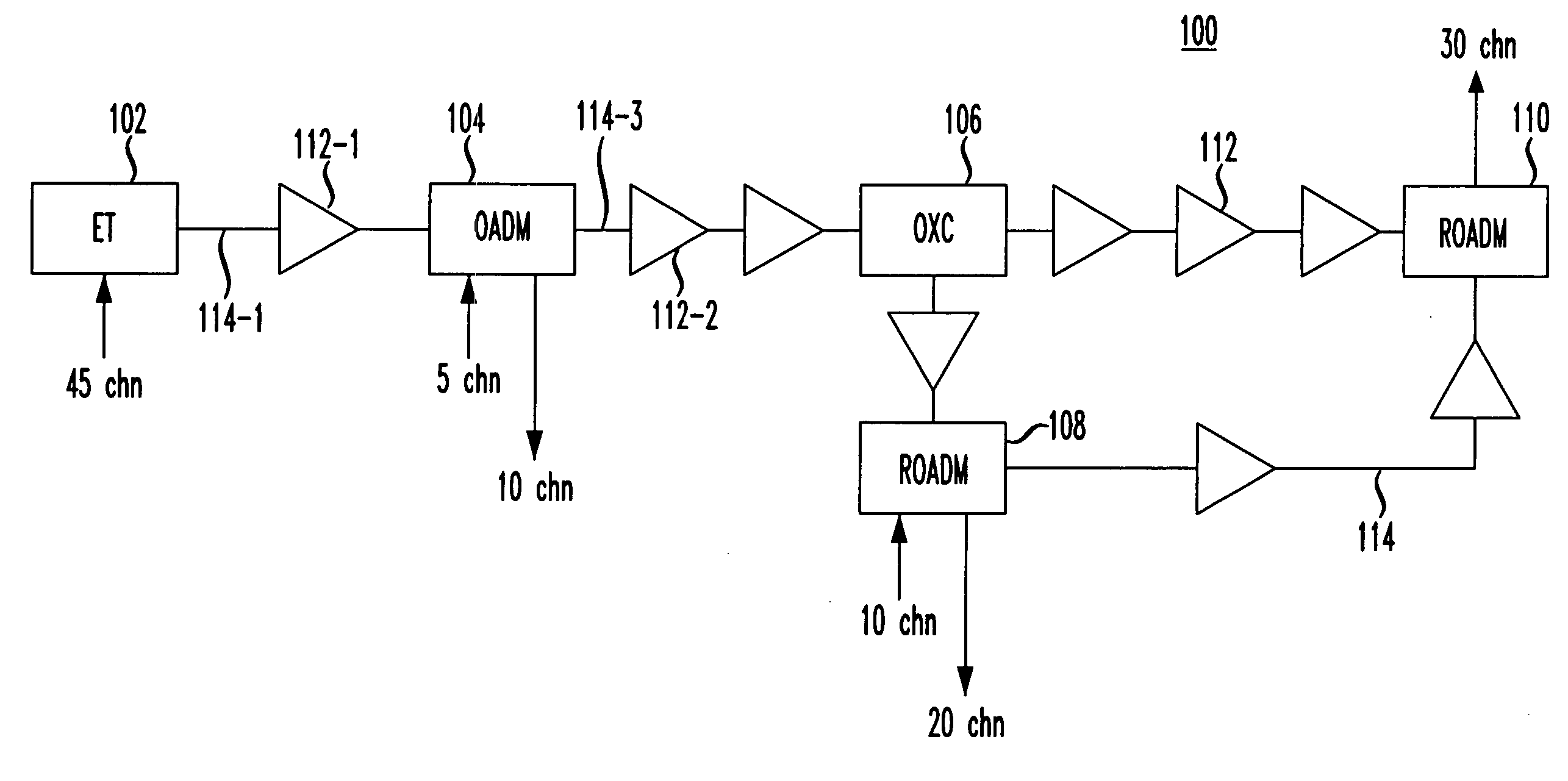
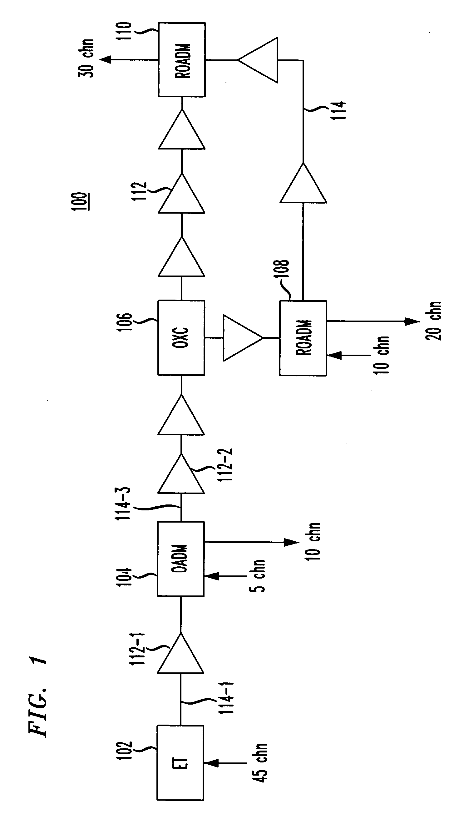
[0022]FIG. 1 shows a block diagram of a portion of an exemplary optical communications system 100 used to illustrate some of the different types of elements for which transient control may be implemented. In particular, FIG. 1 shows a portion of system 100 having five different types of elements (i.e., end terminal (ET) 102, optical add / drop multiplexer (OADM) 104, optical cross-connect (OXC) 106, reconfigurable OADMs (ROADMs) 108 and 110, and eight repeaters 112) interconnected by 14 optical fibers 114.

[0023] In general, an end terminal can add and drop WDM channels, while an OADM can add / drop channels will passing through other channels. An OXC can switch channels to different paths. In addition to being able to add / drop channels, a ROADM can also switch channels to different paths. ROADMs are typically more flexible that OADMs in that ROADMs may be able to add / drop (or pass through) any channel, while OADMs may be able to add / drop only a limited set of channel...


PUM


Abstract

In an optical transmission system, operations of certain elements are adjusted in an individualized manner after detecting a change in the total optical power level corresponding to multiple optical channels in a link of the system in order to control transients in those channels. For example, in response to a sudden drop in the number of channels resulting from a fiber cut, the power levels of the optical pumps in a Raman amplifier in an OADM are adjusted to reduce transient gain errors in the surviving channels, where the adjustment to the pump power level for each different optical pump is a function of both the detected change in the total optical power level and at least one specified coefficient for that particular optical pump, in order to handle non-linearities in the response of the Raman amplifier to the sudden drop in the number of optical channels.

Description

CROSS-REFERENCE TO RELATED APPLICATIONS [0001] This application is one of a set of two U.S. patent applications consisting of Ser. No. 10 / ______ filed as attorney docket no. Kilper 6-1-24-6 and Ser. No. 10 / ______ filed as attorney docket no. Kilper 7-3-1-1-7, both of which were filed on the same date and the teachings of both of which are incorporated herein by reference.BACKGROUND OF THE INVENTION [0002] 1. Field of the Invention [0003] The invention relates to optical transmission systems, and, in particular, to techniques for responding to failures in such systems. [0004] 2. Description of the Related Art [0005] Broadband Raman optical amplifiers are often used in long-reach, wavelength-division multiplexing (WDM) transmission systems. When transparent networking elements such as optical add-drop multiplexers (OADMs) and optical cross-connects (OXCs) are used in such systems, the amplifier power transients resulting from network failures can result in significant power excursions...

Claims


Application Information

Patent Timeline
Patent Type & Authority Applications(United States)
IPC IPC(8): H01S3/00H04B10/29H04J14/02
CPCH04B10/2916H04B10/296H04J14/0221H04J14/0208H04J14/0213H04J14/0201
Inventor KILPER, DANIEL C.MARTELL, CLAUDE A.RAGHAVAN, NARASIMHANSADLER, DAVID A.WHITE, CHRISTOPHER A.
Owner LUCENT TECH INC
Why Eureka
Try Eureka