Sensor array
a sensor array and array technology, applied in the field of analyte test sensors, can solve the problems of increasing the overall complexity and manual dexterity required to use such a system, piercing the skin of the patient, and the above-described glucose measurement procedure requires multiple preparatory steps, so as to achieve the effect of convenient use and low manufacturing cos
- Summary
- Abstract
- Description
- Claims
- Application Information
AI Technical Summary
Benefits of technology
Problems solved by technology
Method used
Image
Examples
first embodiment
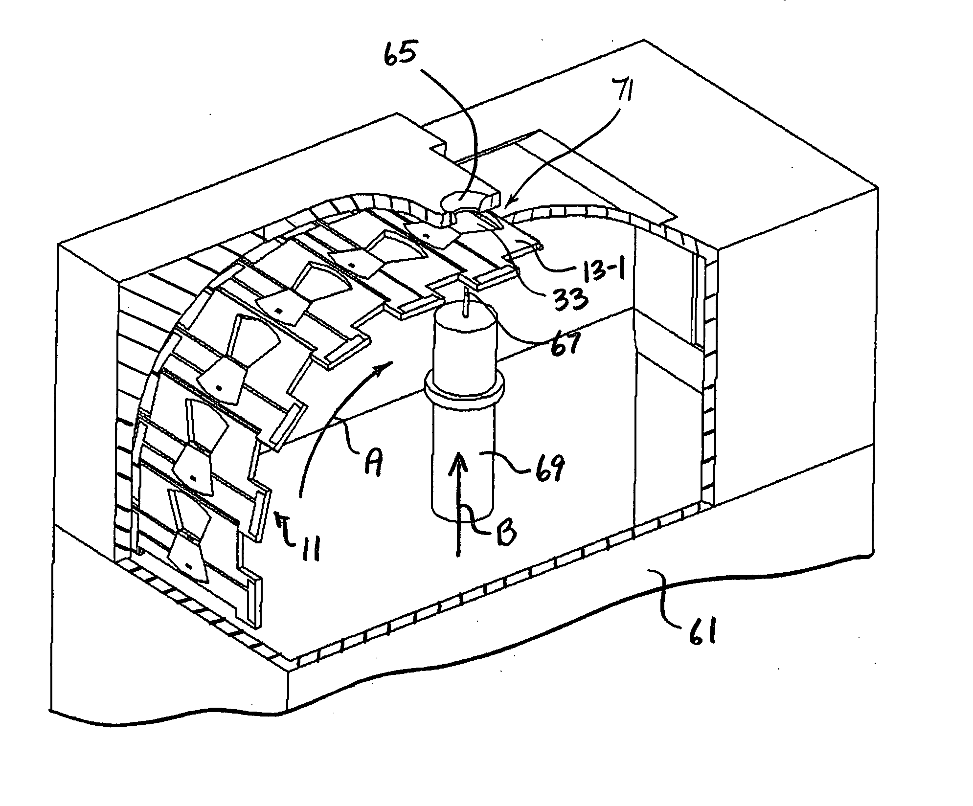
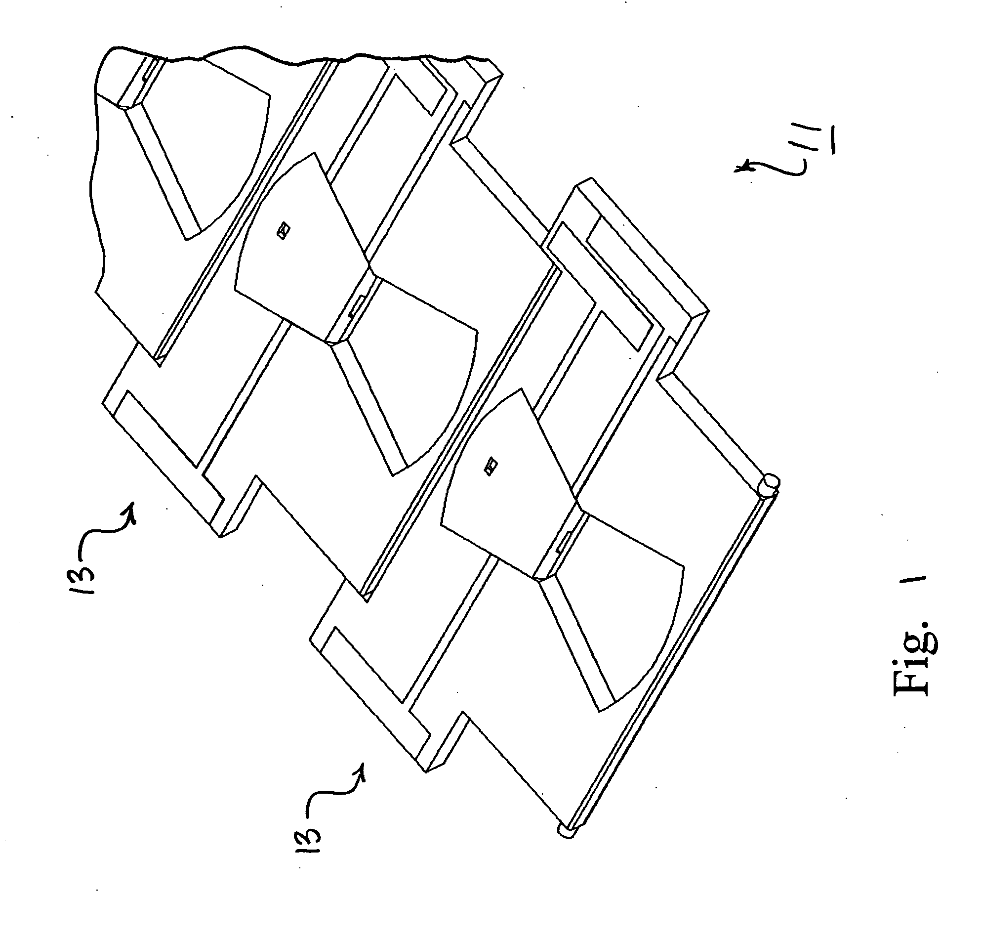
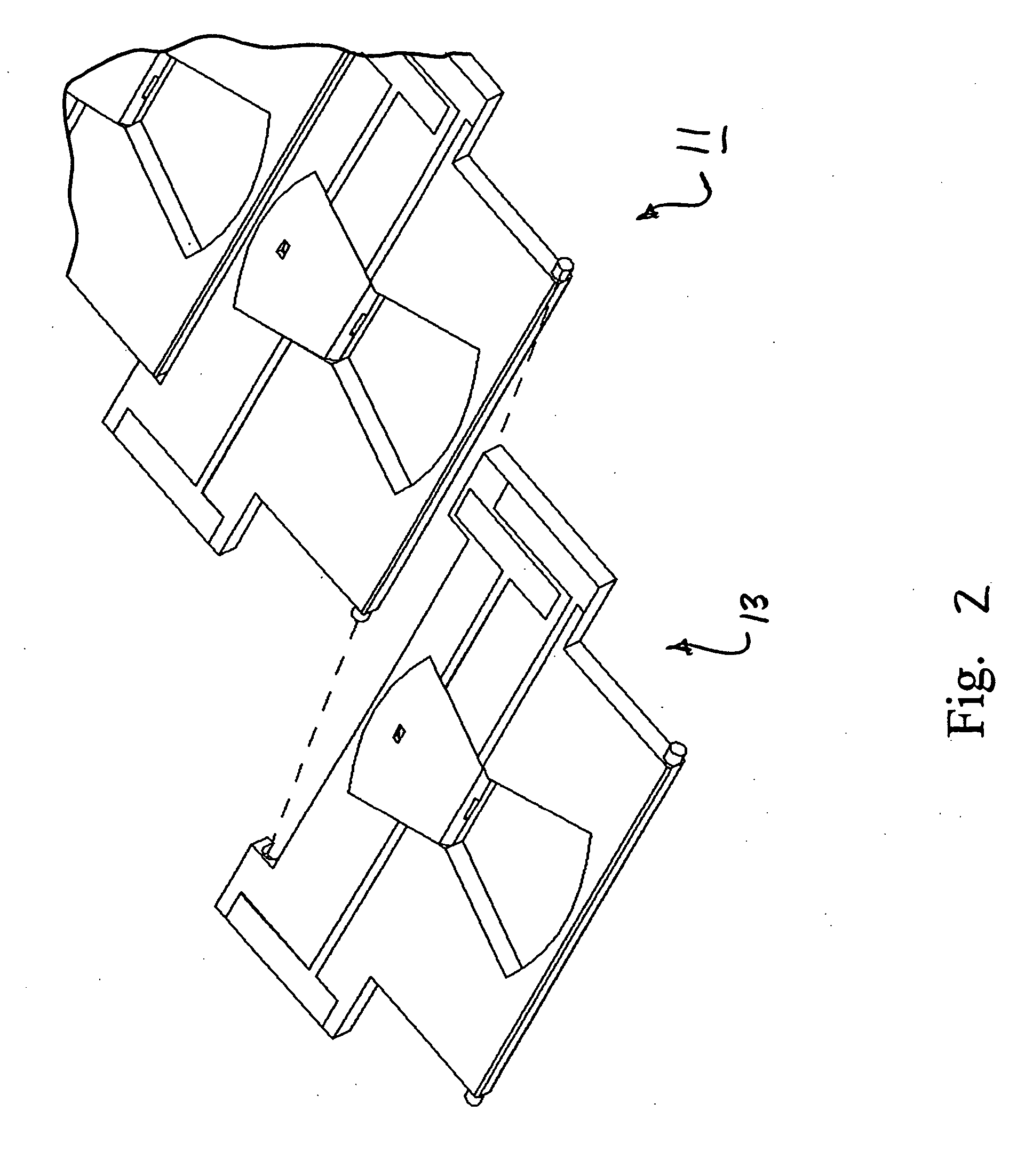
[0046] Referring now to the drawings, there is shown in FIGS. 1-2 a sensor array constructed according to the teachings of the present invention, the sensor array being identified generally by reference numeral 11. As will be described further in detail below, sensor array 11 is designed to be continuously fed into a compatible analyte test monitor. In this manner, a plurality of blood tests can be performed without requiring the user to unwrap and load individual test strips into the test monitor, which is a principal object of the present invention.
[0047] Sensor array 11 includes a plurality of individual analyte test sensors 13 which are hingedly interconnected in a front-to-back arrangement. In this manner, sensor array 11 can be configured to conform to a non-planar surface, as will be described further in detail below.
[0048] Referring now to FIGS. 3-5, each analyte test sensor 13 includes a unitary, non-conductive substrate 15 which is preferably constructed of plastic using ...
second embodiment
[0077] Referring now to FIGS. 9(a) and 9(b), there is shown a sensor array which is constructed according to the teachings of the present invention, the sensor array being identified generally by reference numeral 111. Sensor array 111 is similar to sensor array 11 in that sensor array 111 includes a plurality of test sensors 113 which are arranged in a front-to-back arrangement. However, sensor array 111 differs from sensor array 11 in the manner in which test sensors 113 are interconnected.
[0078] Specifically, sensor array 111 includes a one-piece, non-conductive substrate 115 which is common to each of the test sensors 113. Substrate 115, which is preferably constructed of plastic using conventional molding techniques, includes a substantially flat top surface 117 and a bottom surface 119.
[0079] Substrate 115 is scored at multiple locations to enable sensor array 111 to bend. As seen most clearly in FIG. 9(b), a plurality of laterally extending lines of weakness 121 are formed i...
third embodiment
[0084] Referring now to FIGS. 10 and 11, there is shown a sensor array which is constructed according to the teachings of the present invention, the sensor array being identified generally by reference numeral 211. Sensor array 211 includes a plurality of individual test sensors 213 which are spaced apart from one another and are configured in a parallel, front-to-back arrangement.
[0085] Each test sensor 213 includes a unitary, non-conductive substrate 215 which is preferably constructed of plastic using conventional molding techniques. Substrate 215 is preferably in the form of a thin, rectangular strip which includes a substantially flat top surface 217, a substantially flat bottom surface 219, a front edge 221, a back edge 223, and a pair of side edges 225. However, it is to be understood that the particular shape of substrate 215 could be modified without departing from the spirit of the present invention.
[0086] A pair of carbon-layer electrodes 227-1 and 227-2 are deposited on...
PUM
 Abstract
Description
Claims
Application Information
 - R&D
- Intellectual Property
- Life Sciences
- Materials
- Tech Scout
- Unparalleled Data Quality
- Higher Quality Content
- 60% Fewer Hallucinations
Browse by: Latest US Patents, China's latest patents, Technical Efficacy Thesaurus, Application Domain, Technology Topic, Popular Technical Reports.
© 2025 PatSnap. All rights reserved.Legal|Privacy policy|Modern Slavery Act Transparency Statement|Sitemap|About US| Contact US: help@patsnap.com


