Methods for sputtering a target material by intermittently applying a voltage thereto and related apparatus, and methods of fabricating a phase-changeable memory device employing the same

a technology of target material and sputtering method, which is applied in the direction of electrolysis components, vacuum evaporation coatings, coatings, etc., can solve the problems of arcing, affecting the stability of sputtering, so as to reduce the deposition rate of chalcogen compound layer, reduce the deposition rate, and increase the reaction time

Inactive Publication Date: 2006-02-09
SAMSUNG ELECTRONICS CO LTD
View PDF6 Cites 69 Cited by
  • Summary
  • Abstract
  • Description
  • Claims
  • Application Information

AI Technical Summary

Benefits of technology

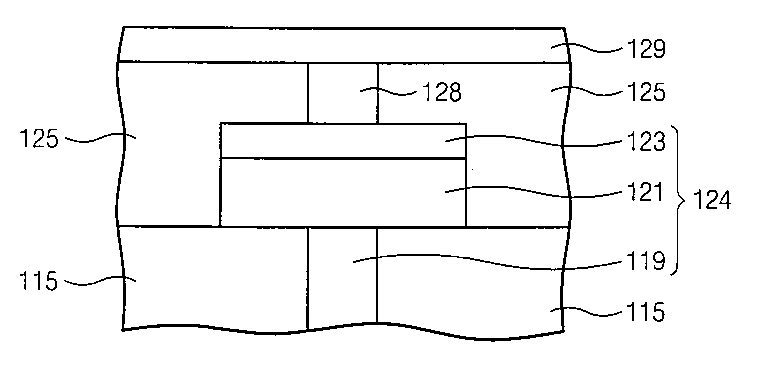
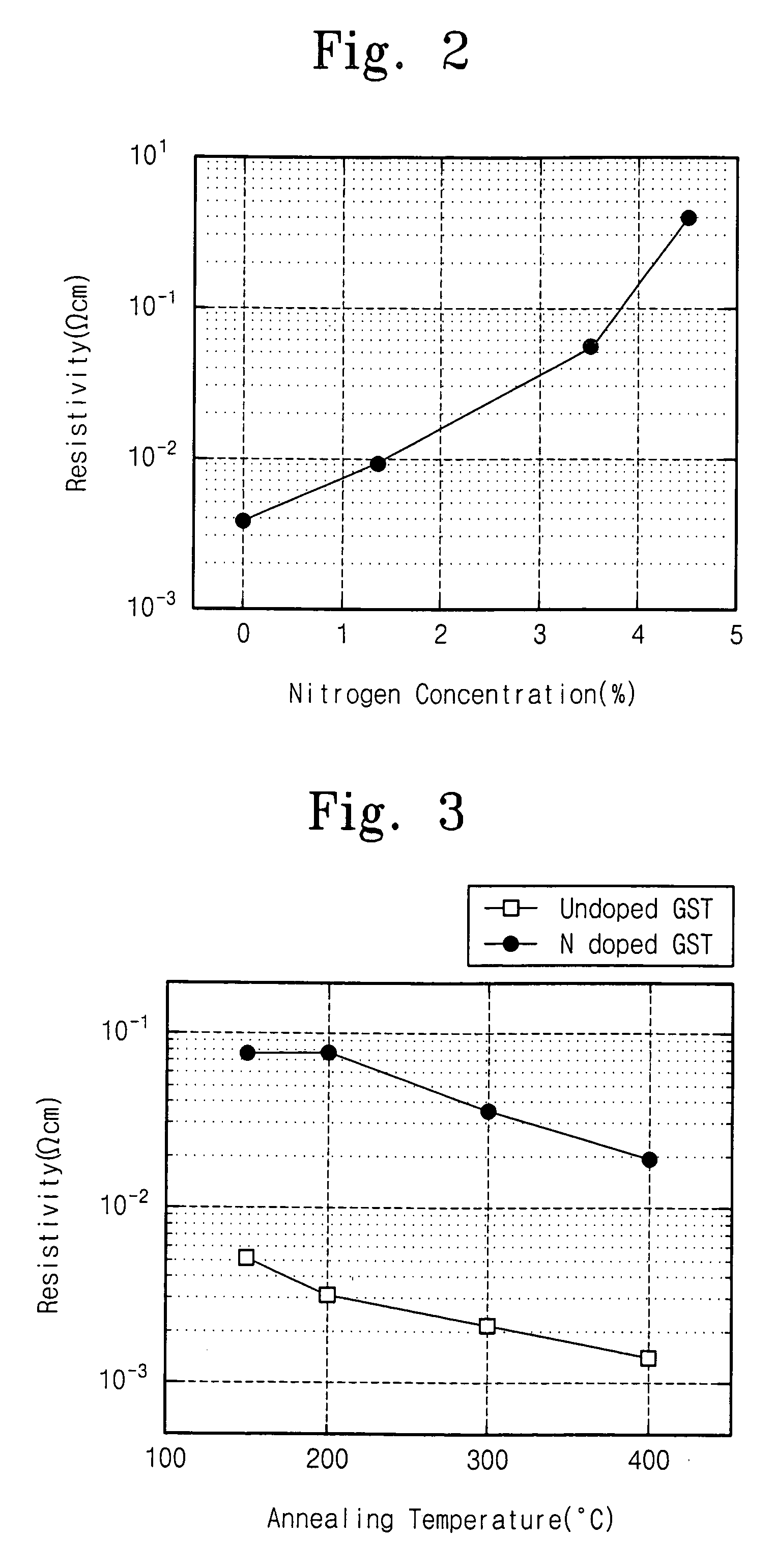
[0028] In other embodiments, periodically applying the positive DC bias may not only decrease a deposition rate of the chalcogen compound layer, but may also increase the reaction time for the nitrogen atoms and the chalcogen compound of the target. A chalcogen compound layer doped with nitrogen atoms having a smaller crystal size may thereby be formed on the substrate, as the sputtered atoms of the target and the nitrogen radical may be sufficiently reacted. A chalcogen compound layer with a smaller crystal size may require a decreased reset / set current in order to convert the chalcogen compound into a solid and / or amorphous state as compared with thin films having a relatively large crystal size. Moreover, a chalcogen compound doped with nitrogen atoms and silicon atoms may have a relatively small crystal size as compared with chalcogen compounds not doped with nitrogen atoms and / or silicon atoms.

Problems solved by technology

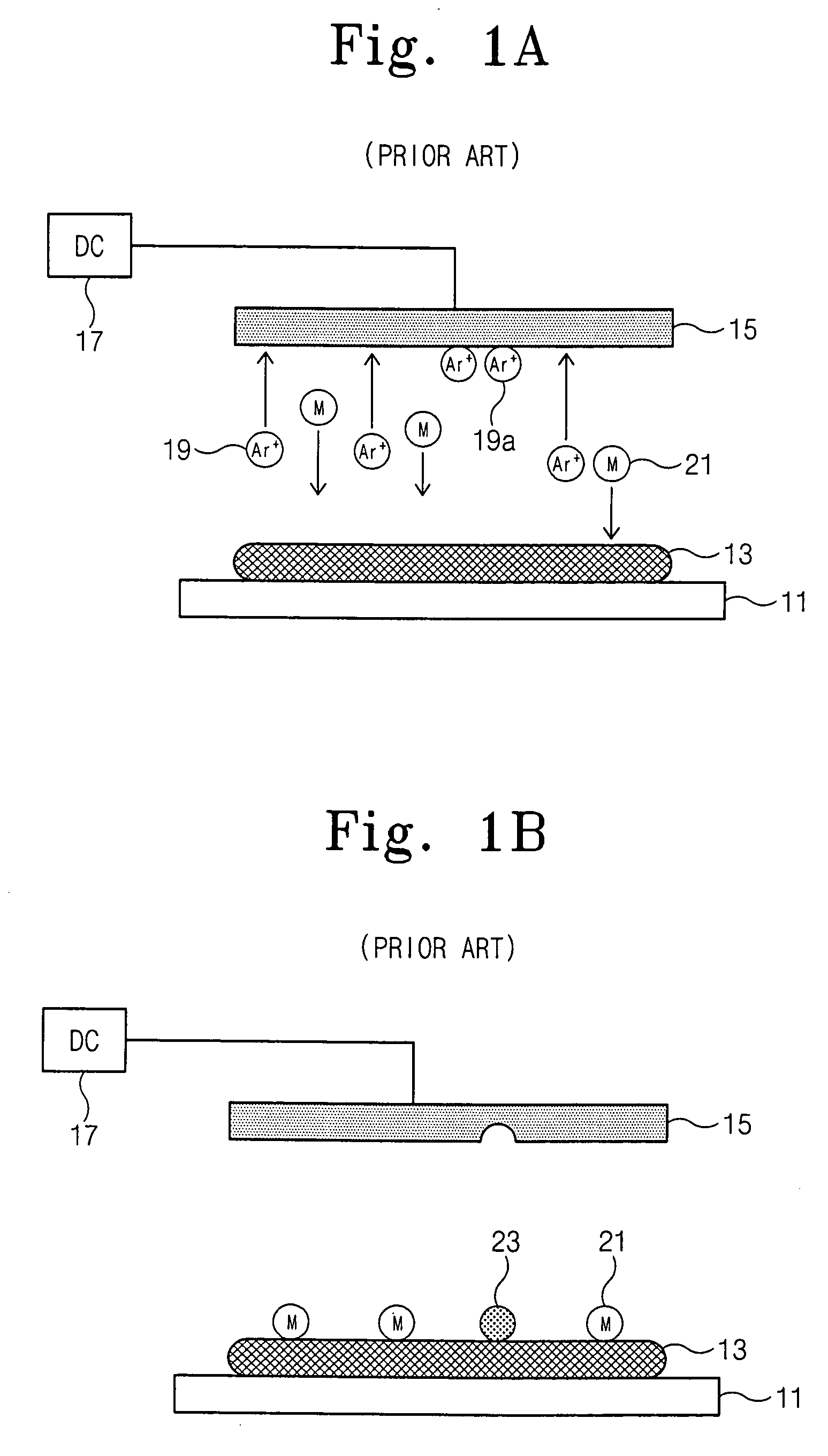
A potential problem associated with sputtering is arcing.
For example, in forming a conductive layer by DC sputtering, a surface of the target may become polluted, such that an insulating layer may be formed on portions of the surface of the target.
The accumulated argon ions at the surface of the target may cause arcing, such that a portion of the target may melt and become attached to the surface of the substrate.
Especially in materials that melt at lower temperatures than metal (for example, chalcogen), the arcing may present serious problems.
As a result, it may be difficult to form a chalcogen compound layer (or other phase-changeable material layer) having excellent properties using conventional DC sputtering methods.

Method used


Image

  • Methods for sputtering a target material by intermittently applying a voltage thereto and related apparatus, and methods of fabricating a phase-changeable memory device employing the same
  • Methods for sputtering a target material by intermittently applying a voltage thereto and related apparatus, and methods of fabricating a phase-changeable memory device employing the same
  • Methods for sputtering a target material by intermittently applying a voltage thereto and related apparatus, and methods of fabricating a phase-changeable memory device employing the same

Examples


Embodiment Construction

[0041] The present invention now will be described more fully hereinafter with reference to the accompanying drawings, in which embodiments of the invention are shown. However, this invention should not be construed as limited to the embodiments set forth herein. Rather, these embodiments are provided so that this disclosure will be thorough and complete, and will fully convey the scope of the invention to those skilled in the art. In the drawings, the thickness of layers and regions are exaggerated for clarity. Like numbers refer to like elements throughout.

[0042] It will be understood that when an element such as a layer, region or substrate is referred to as being “on” or extending “onto” another element, it can be directly on or extend directly onto the other element or intervening elements may also be present. In contrast, when an element is referred to as being “directly on” or extending “directly onto” another element, there are no intervening elements present. It will also ...


PUM

PropertyMeasurementUnit
frequencyaaaaaaaaaa
melting pointaaaaaaaaaa

Abstract

A method of sputtering to deposit a target material onto a substrate includes supplying an ionized gas to the substrate and the target material. A first DC bias voltage having a polarity opposite that of the ionized gas is applied to the target material to attract ions theretoward. A second DC bias voltage having a polarity opposite that of the first DC bias voltage is intermittently applied to the target material to reduce ion accumulation thereon. Related apparatus and methods of fabricating phase-changeable memory devices are also discussed.

Description

CROSS-REFERENCE TO RELATED APPLICATIONS [0001] This application claims priority under 35 U.S.C. § 119 from Korean Patent Application No. 10-2004-0062165 filed on Aug. 6, 2004, the disclosure of which is hereby incorporated by reference herein in its entirety. BACKGROUND OF THE INVENTION [0002] The present invention relates to semiconductor device fabrication methods, and more particularly, to sputtering methods and related devices. [0003] DC sputtering technology has been widely used in methods for forming a thin film on a substrate. More particularly, DC sputtering technology has been applied in a variety of industrial fields, for example, in semiconductor manufacturing processes. In DC sputtering, a vacuum atmosphere may be provided in a chamber including a target material disposed over a substrate. A negative DC voltage may be applied between the target and the substrate. Argon gas may then be introduced into the chamber and ionized. As such, the argon gas ions may be accelerated...

Claims


Application Information

Patent Timeline
Patent Type & Authority Applications(United States)
IPC IPC(8): C23C14/34C23C14/32
CPCC23C14/34C23C14/345C23C14/35H01L45/1625H01L45/06H01L45/1233H01L45/144H01L27/2436H10B63/30H10N70/231H10N70/826H10N70/8828H10N70/026H01L21/203H10B99/00
Inventor PARK, JEONG-HEELEE, JANG-EUNCHO, SUNG-LAE
Owner SAMSUNG ELECTRONICS CO LTD
Why Eureka
Try Eureka