Cold cathode ion gauge

a cathode ion gauge and gauge technology, applied in vacuum gauges, fluid pressure measurement, instruments, etc., can solve the problems of increasing the probability of collisions with gases in the gauge, losing sensitivity in a high vacuum, and gas in the vacuum chamber chemically reacting, etc., to achieve the effect of prolonging li

Active Publication Date: 2006-08-29
FEI CO
View PDF13 Cites 11 Cited by
  • Summary
  • Abstract
  • Description
  • Claims
  • Application Information

AI Technical Summary

Benefits of technology

[0011]An object of the invention is to provide a CCIG with extended life.
[0014]Various aspects of the invention mitigate the detrimental effects of the unfriendly gases in various ways, typically by reducing the current density within the gauge, such as by reducing the total current and / or by increasing the area of one or both electrodes. Reducing the current density reduces the deposition rate (thickness per area per unit time), thereby increasing the life of the gauge. Other embodiments construct the electrode from materials that reduce the detrimental effects of the gases. Such preferred materials can, for example, reduce the ionization current by reducing electron backscattering and secondary electron emission. Other preferred materials can remove contaminants or oxygen by “gettering” or by forming benign, volatile by-products. Other materials can be readily cleaned of any deposition and quickly returned to service.

Problems solved by technology

A Pirani gauge can effectively measure pressure from a low vacuum up to atmosphere, but loses sensitivity in a high vacuum.
An HCIG can measure a wide range of vacuums, but the hot filament produces heat, which can cause gases in the vacuum chamber to chemically react to produce compounds that promote contamination and corrosion.
The magnetic field, which produces a force on charged particles perpendicular to their velocities, causes the charged particles to traverse a meandering path, which increases the probability of collisions with gases in the gauge.
In a lower vacuum range from about 10−4 Torr to about 10−2 Torr, the greater concentration of gas molecules creates a very large ionization current, which causes excessive heat and sputtering of materials from the electrodes.
While known solutions exist for using CCIGs at low vacuum, in most applications CCIGs operate reliably in a high vacuum with a long lifetime.
In some high vacuum applications, however, CCIGs tend to fail after a relatively short period of use.
Although the gas pressure in such application is sufficiently low to avoid excessive heat and sputtering, CCIGs in such applications can still suffer a short average lifetime of about two weeks.
Typical failures, which can occur after between two weeks and a few months of operation, are manifested as questionable vacuum readings, unstable vacuum readings, and malfunctions of the gauge.
The problem of short CCIG lifetimes when operating at high vacuum, such as pressures less than about 10−4 Torr, less than about 10−5 Torr or less than about 10−6 Torr, has not been solved because the mechanism for failure at the low pressures was unknown.

Method used


Image

  • Cold cathode ion gauge
  • Cold cathode ion gauge
  • Cold cathode ion gauge

Examples


Embodiment Construction

[0028]The invention solves the problem of reduced CCIG useful life at low pressures. The present invention is particularly suited for measuring high vacuum containing unfriendly gases that could cause deposition, corrosion, or other problems. Such gases are typically introduced into the system for use with charge-particle beams, for example, in a circuit edit or mask repair process, for charged particle beam induced deposition or etching. The invention is particularly suitable for use in a vacuum system having a pressure less than about 10−5 Torr, particularly in the high vacuum range of 10−6 to 10−5 Torr. While the invention solves problems related to vacuum systems using unfriendly gases at high vacuums, the invention is not limited to those applications and aspects of the invention can be beneficially applied to vacuum gauges in other vacuum systems.

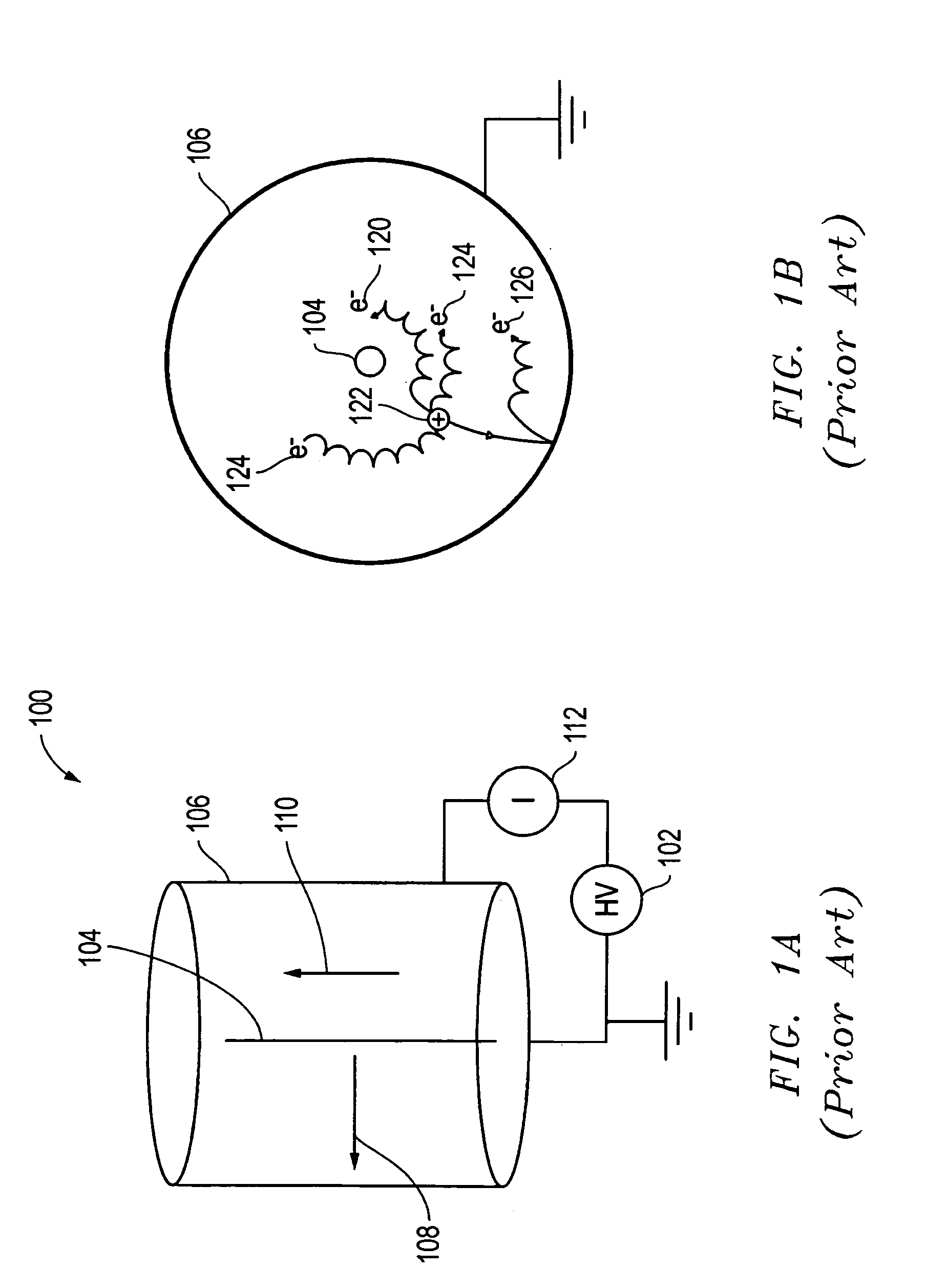
[0029]Applicant has discovered that the degradation CCIGs in an environment of unfriendly gases can be caused by the charged-particl...


PUM

PropertyMeasurementUnit
pressureaaaaaaaaaa
discharge current densityaaaaaaaaaa
current densityaaaaaaaaaa

Abstract

A cold cathode ion gauge is provided that is suitable for use in a high vacuum and in the presence of contaminating gases. By decreasing the discharge current and, more precisely, decreasing the charge current density received by the gauge electrodes, and using certain type of materials for the gauge electrodes, the mechanism by which insulating films are deposited on surface of the electrodes is attenuated and the life of the gauge is significantly prolonged. The gauge discharge current can be decreased by providing a large resistor in series with the anode, while the charge current density can be decreased by using an electrode with larger surface area, which can be achieved by fabricating grooves or fans on electrodes and by using low electron backscattering and low secondary emission materials, like carbon.Another concept of constant current mode is also proposed in this invention for extending the lifetime of CCIGs that are used for vacuum containing unfriendly gases.

Description

[0001]This application claims priority from U.S. Provisional Patent Application No. 60 / 533,680, filed on Dec. 31, 2003 and from 60 / 536,060, filed Jan. 13, 2004 both of which are hereby incorporated by reference.TECHNICAL FIELD OF THE INVENTION[0002]The present invention relates to gauges for measuring vacuum, particularly gauges for use in high vacuum systems.BACKGROUND OF THE INVENTION[0003]Many industrial applications require processing in a vacuum, from a ultra high vacuum (“UHV”), that is, a very low gas pressure of less than about 10−8 Torr, to a rough vacuum, in which the pressure can be almost as high as atmospheric pressure. The terms “vacuum” and “pressure” are used in opposite senses, in that a “high vacuum” means a “low pressure” and vice versa.[0004]Different types of vacuum gauges are used to measure vacuum in different pressure ranges. For example, a Pirani gauge is suitable for use in a vacuum from 10−5 Torr (1.3×10⁻³ Pa) to atmospheric pressure; a hot cathode ion gau...

Claims


Application Information

Patent Timeline
Patent Type & Authority Patents(United States)
IPC IPC(8): G01L21/30G01L21/34
CPCG01L21/34H01J41/06
Inventor LIU, KUN
Owner FEI CO
Why Eureka
Try Eureka