
Vision thermalization for sightless & visually impaired

a vision thermalization and sightless technology, applied in closed circuit television systems, television systems, instruments, etc., can solve the problems of vt profits becoming disruptive to the status quo, science and technology have not yet fully perfected retina implants, and the date provides limited sight restoration

Inactive Publication Date: 2006-02-09
STAPLEVISION LLC
View PDF10 Cites 13 Cited by
  • Summary
  • Abstract
  • Description
  • Claims
  • Application Information

AI Technical Summary

Benefits of technology

"The present invention is a technology that aims to provide sightless and visually impaired individuals with the full fidelity and image integrity of normal vision. It does this by transforming light waves to heat waves of IR images and receiving, decoding, and encoding remote or direct video while utilizing the dynamic range and temperature sensitivity of IR images. The invention also provides enhancements to image quality, such as adaptive nonlinear grayscale correction, and buffer storage for variable refreshing rates of images to optimize power dissipation. Additionally, the invention allows for the expansion of benefits under the American Disability Act by providing technology for the sightless to see PC displays, internet, palm pilots, and more. The invention also incorporates feedback command and control for laboratory and factory testing and provides a means to transform light waves to heat waves of IR images. Overall, the invention improves the quality of life for the sightless and visually impaired by enhancing their ability to see and interact with the world around them."

Problems solved by technology

Present medical science and technology have not yet quite perfected retina implants which to date provide limited restoration of sight for a limited number of the sightless and visually impaired, due to various eye diseases, despite all the good intentions in the world, altruism, philanthropy etc.
Obviously VT profits may become disruptive to the status quo and marketplace of white canes, seeing-eye-dogs, audio descriptors of TV, and Braille, whose tactile signals have reportedly been traced through the visual cortex.

Method used


Image

  • Vision thermalization for sightless & visually impaired
  • Vision thermalization for sightless & visually impaired
  • Vision thermalization for sightless & visually impaired

Examples


Embodiment Construction

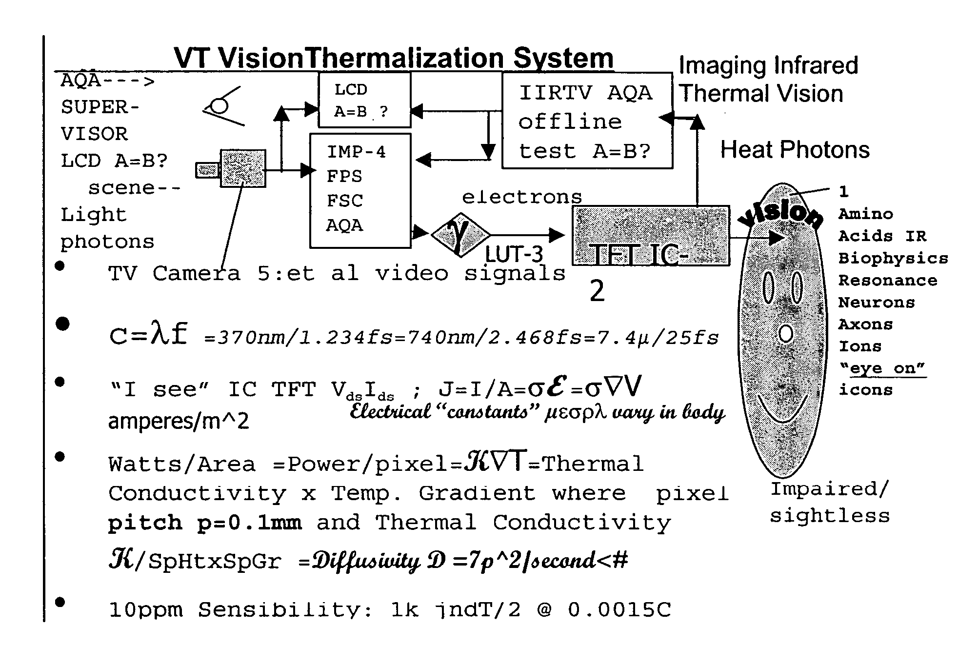
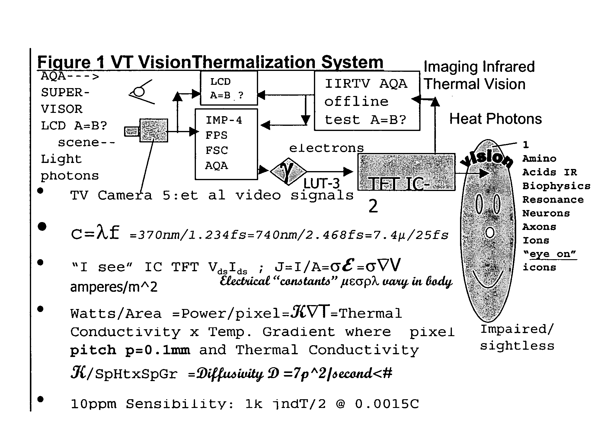
[0038] Nonlinear optimization dictates that one design such grossly nonlinear vision systems “backwards” starting with the last stage first24, that is the eye-brain 1, then the display 2, image processor 3, sensor 4 then illuminator 5. Accordingly in FIG. 1, since signal flow generally goes left to right, the key items of the VT system are labeled 1 to 5 from right to left. How does the touch signal in brain from Braille get processed via the visual cortex? Should not the “grass roots” ganglion cells in the thin film display called the retina operate like those beneath the forehead skin25 processing sensible heat signals rather than the retina photodetector signals?

24Operations Research

25ganglion cells

[0039] Humans vision normally is limited to less than one octave of the electromagnetic spectrum 370-740 nanometers (nm), centered about 555 nm where color discrimination is weakest because the peak daylight (photopic) response 683 Lumens / watt equals the twilight (scotopic) response....


PUM


Abstract

A Vision Thermalization, “VT” light-to-heat transducer, versatile video transformation system, via Biophysics Resonance of forehead cells with thin film transistors infrared “display” (1k×0.0015C×640×480 VGA) and alternative image processing methodology thereof to convert, for the sightless and visually impaired, light waves, or TV received signals or 2D / 3D video camera signals into infrared patterns of sensible heat waves such as produced by the product of voltage and current in an active matrix of thin film transistors (AM-TFT), typically used with liquid crystal displays, in order to exploit the viper-like thermal vision sensibility of 10 parts / million (0.003C / 305K) and biophysics resonance of thermo regulating amino acids.

Description

FIELD OF THE INVENTION [0001] The present Vision Thermalization (VT hereinafter) invention is directed towards light to heat versatile video transformation system and alternative image processing methodology thereof to convert for the sightless and visually impaired light waves, TV received signals or 2D / 3D video camera signals for the purpose of making infrared patterns of heat waves such as produced1 by the product of voltage and current in an active matrix of thin film transistors (AM-TFT) typically used with liquid crystal displays thereby exploiting the human forehead's viper-like thermal vision sensibility2 of 10 parts / million (0.003 C / 305K) and biophysics resonance3 with the infrared quantum vibrations or rotations of inhibitor and excitor amino acids4 communicating the thermoregulator error signals and control feedback5 analogous to normal sight. 1a Hughes patent teaches how video can be projected as IR image 2sc am 3biophysics resonance is defined herein as 4aa 5feedback BA...

Claims


Application Information

Patent Timeline
Patent Type & Authority Applications(United States)
IPC IPC(8): H04N7/18H04N9/47
CPCA61F9/08G09B21/003G09B21/001
Inventor STAPLETON, JOHN J.
Owner STAPLEVISION LLC
Learn More