Cavity monitoring device for pulse laser

a monitoring device and pulse laser technology, applied in the direction of laser monitoring arrangements, laser details, wave amplification devices, etc., can solve the problems of reducing the failure rate of the system, requiring additional components, and making the polarizer and wave plate unnecessary

Inactive Publication Date: 2006-02-09
IMRA AMERICA
View PDF8 Cites 27 Cited by
  • Summary
  • Abstract
  • Description
  • Claims
  • Application Information

AI Technical Summary

Benefits of technology

[0016] A saturable absorber fabricated of semiconductor is used for passive mode-locking of an Er-doped fiber laser. The absorber layer is combined with a reflective device, such as dielectric mirror, metal mirror or semiconductor Bragg reflector in order to provide the functionality of a cavity mirror positioned at one end of the gain fiber. The transmittance of the mirror device is adjusted in order to leak light out of the cavity. The leakage light is used exclusively for monitoring laser performance. The extraction of the cavity light for the laser application is realized by another cavity mirror, positioned at the other end of the gain fiber. A partially reflective mirror structure or a fiber Bragg grating is used for the output coupler. The objectives for monitoring are the repetition rate of the laser pulse, power level and the verification of the mode-locking or Q-switching operation. The invention also discloses a method for integration of a photo sensor with the saturable absorber modulator into one package.

Problems solved by technology

Moreover, the composite failure rate of the system drops, which in turn enhances the yield and productivity of manufacturing of such laser systems.
One challenging task in the arena of laser technology is to bring ultrashort lasers within the realm of industrial manufacturing.
In practice, however, additional components are usually required.
The use of polarization maintaining fiber makes the polarizer and wave plate unnecessary.
However, this approach requires the unnecessary complexity of fabricating an electrically active semiconductor device.
Furthermore, the size constraint, below 1 mm2, in order to resolve a pulse train ranging from tens of megahertz to hundreds of megahertz, makes the assembly of the absorber in a cavity difficult.
Here, not only is the additional component a drawback, but also the extra fiber pigtail length is a disadvantage.
Any additional fiber dispersion can cause difficulties in delivering ultrashort pulses of a few hundreds of femtoseconds.
Perfect compensation of fiber dispersion for a broad (>10 nm) spectral femtosecond pulse is well known to be challenging in the laser community.
Due to the complexity of such system, the cavity performance needs to be monitored during operation in order to prevent malfunction, which can result in costly damage of the system and the application.
A failure of mode-locking can cause catastrophic damage to the amplifier.

Method used


Image

  • Cavity monitoring device for pulse laser
  • Cavity monitoring device for pulse laser
  • Cavity monitoring device for pulse laser

Examples


Embodiment Construction

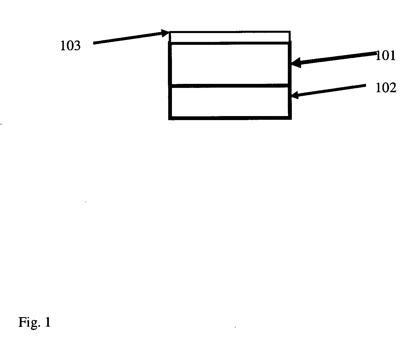
[0017] The preferred laser is a linear fiber cavity pumped by one or more laser diodes. It comprises a gain fiber with an Er and / or Yb dopant, an output coupling device comprising either a partial reflectance mirror or fiber Bragg grating, and a saturable absorber modulator with a reflective device. The extraction of the laser pulse out of the cavity is realized by the output coupling mirror. The transmittance of such an output mirror is typically larger than 10%. The high gain in the fiber requires a relatively high transmission rate compared to a solid state laser, where a rate of few percent is common. The preferred saturable absorber is fabricated out of InP-related semiconductor. For Er doped fiber, a bulk layer of InGaAsP grown on an InP substrate is preferred. However, a quantum well absorber is another preference. A reflective device (102) is attached beneath the absorber layer (101). A dielectric coating (103), usually an anti-reflection coating, is deposited on the absorbe...


PUM


Abstract

A fiber laser system is provided with a laser cavity including at least a gain fiber, an output coupling mirror, and a saturable absorber mirror. A photo sensor detects leakage light passing through the saturable absorber mirror, for purposes of monitoring the performance of the laser system. The saturable absorber mirror may include a semiconductor saturable absorber having a Bragg reflector monolithically formed on one side thereof.

Description

FIELD OF THE INVENTION [0001] The present invention relates to a monitor for detecting performance prameters of a pulsed laser. In particular the invention is for a fiber laser cavity with a saturable absorber modulator. BACKGROUND OF THE INVENTION [0002] A compactly packaged laser cavity with a minimum number of components has a number of advantages. It stimulates a broader application market where the small form factor of the laser is a considerable advantage; for example for integration into a portable instrument. Also the small form factor reduces mechanical instability, allowing operation over a wide range of mechanical perturbation than a solid-state laser can allow. Moreover, the composite failure rate of the system drops, which in turn enhances the yield and productivity of manufacturing of such laser systems. [0003] One challenging task in the arena of laser technology is to bring ultrashort lasers within the realm of industrial manufacturing. One advantage of fiber lasers ...

Claims


Application Information

Patent Timeline
Patent Type & Authority Applications(United States)
IPC IPC(8): H01S3/30
CPCH01S3/067H01S3/08009H01S3/0014H01S3/1118H01S3/1312H01S3/0941
Inventor CHO, GYU CHOENOHTAKE, HIDEYUKIOHTA, MICHIHARU
Owner IMRA AMERICA
Why Eureka
Try Eureka