Refrigerant cycle apparatus
a cycle apparatus and refrigerant technology, applied in mechanical apparatus, refrigeration components, light and heating apparatus, etc., can solve the problems of difficult to obtain desired throttling effect, performance degradation, and increase compressive power, so as to reduce the pressure loss in the evaporator, reduce the compressive power, and enhance the performance coefficient
- Summary
- Abstract
- Description
- Claims
- Application Information
AI Technical Summary
Benefits of technology
Problems solved by technology
Method used
Image
Examples
embodiment 1
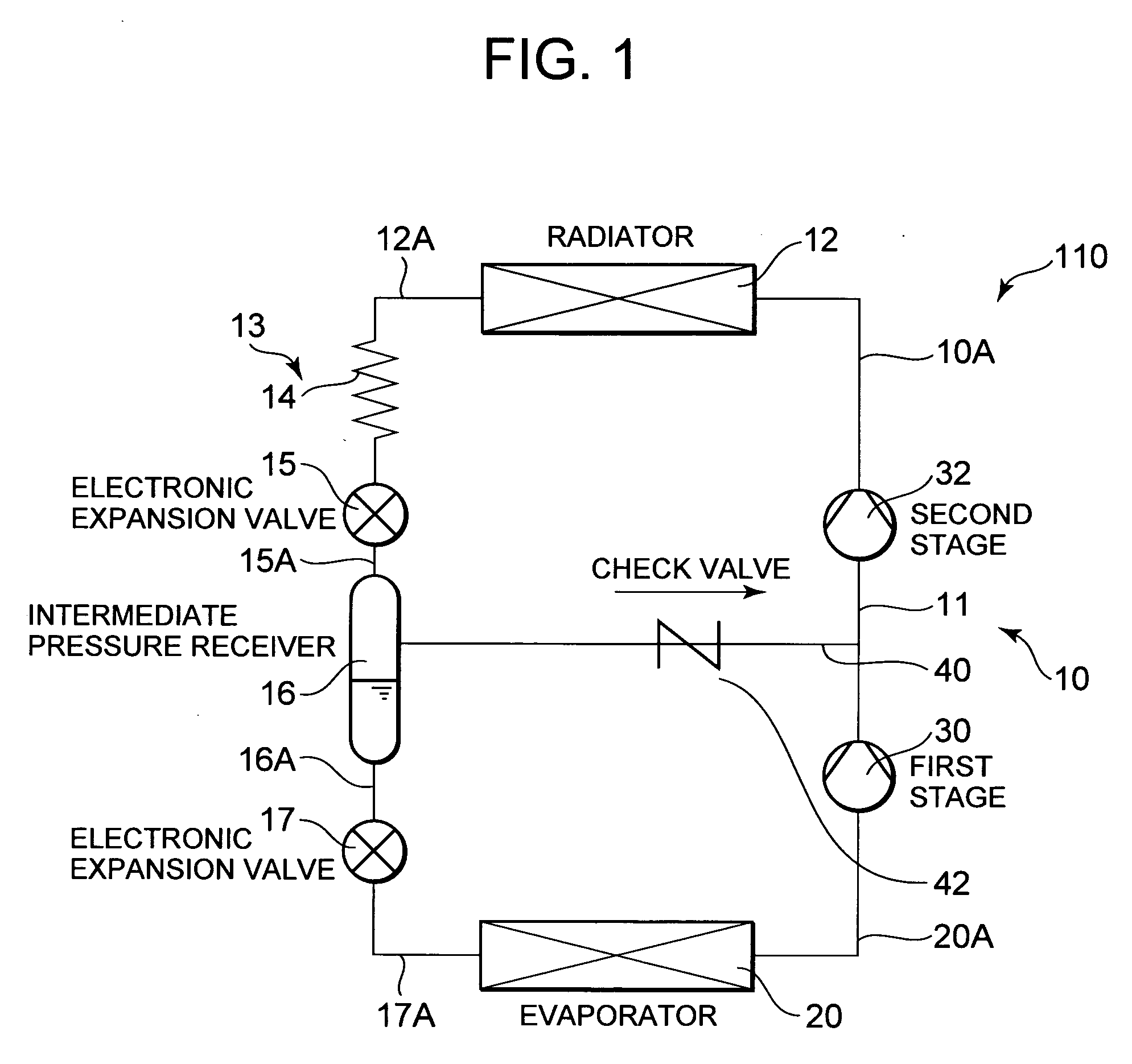
[0023]FIG. 1 is a refrigerant circuit diagram of a refrigerant cycle apparatus 110 according to one embodiment of the present invention. In the refrigerant cycle apparatus 110 of the present embodiment, a compressor 10, a radiator 12, a first pressure reducing device 13, an intermediate pressure receiver 16, a second pressure reducing device 17, and an evaporator 20 are successively connected to one another in an annular form to constitute a refrigerant circuit. That is, a refrigerant discharge tube 10A of the compressor 10 is connected to an inlet of the radiator 12.
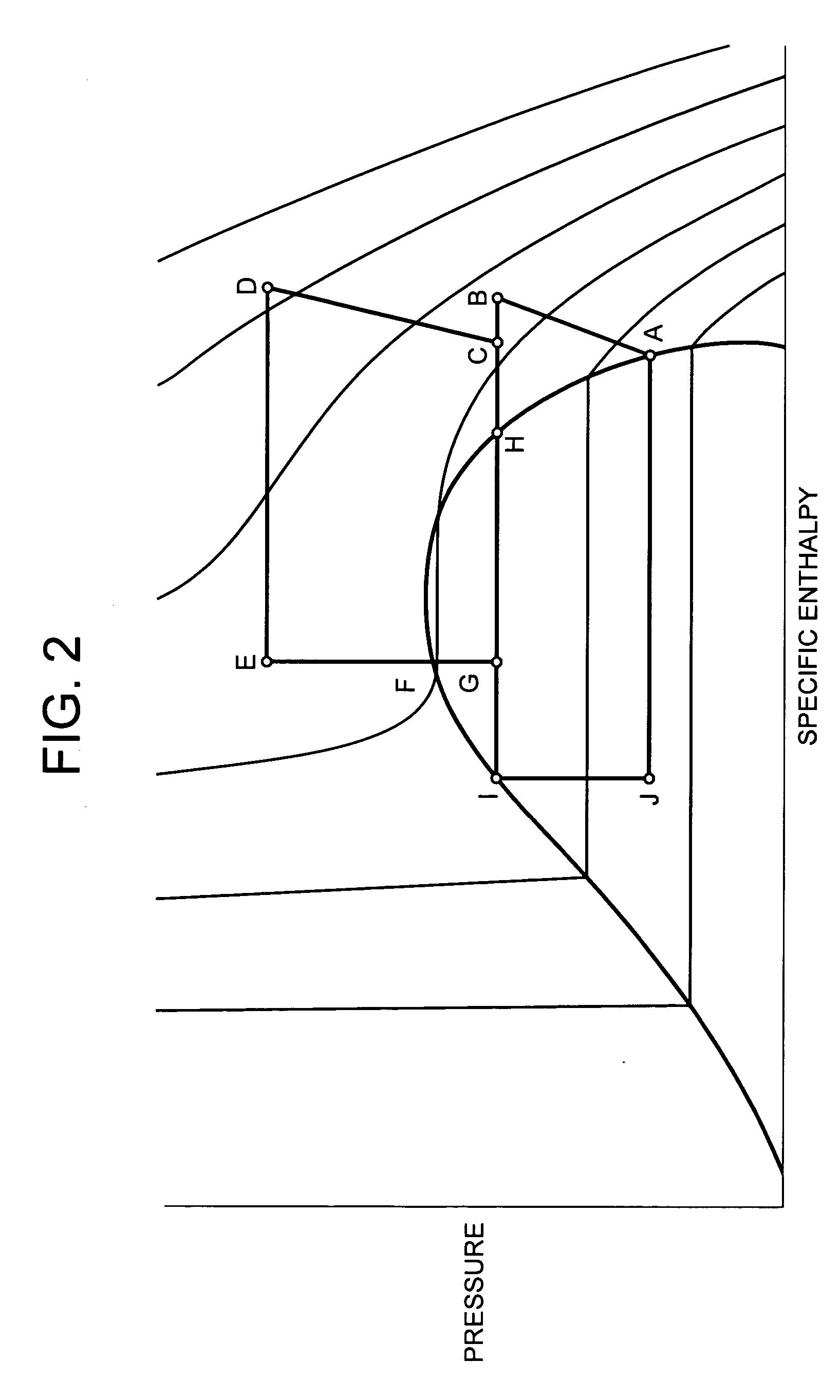
[0024] Here, the compressor 10 of the present embodiment is a compressor of a two-stage compression system, having a first compression element 30 and a second compression element 32 for compressing a refrigerant compressed by the first compression element 30. In a sealed container (not shown), there are arranged a driving element, and the first compression element 30 and the second compression element 32 which are driv...
embodiment 2
[0048] Next, a second embodiment of a refrigerant cycle apparatus according to the present invention will be described. FIG. 3 is a refrigerant circuit diagram of a refrigerant cycle apparatus 210 of the present embodiment. It is to be noted that, in FIG. 3, components denoted with the same reference numerals as those of FIG. 1 produce identical or similar effects.
[0049] In FIG. 3, reference numeral 25 denotes a capillary tube which is throttling means of a first pressure reducing device 13 in the present embodiment. This capillary tube 25 has an inner diameter of 0.5 mm or more and 6 mm or less, and a dimension of 0.5 m or more and 2 m or less, and has heretofore been used.
[0050] That is, as described above in detail in the first embodiment, a refrigerant having a supercritical state is first pressure reduced by a capillary tube 14 having a small inner diameter, and accordingly the refrigerant can be sufficiently pressure reduced. Therefore, even when the conventional tube is use...
embodiment 3
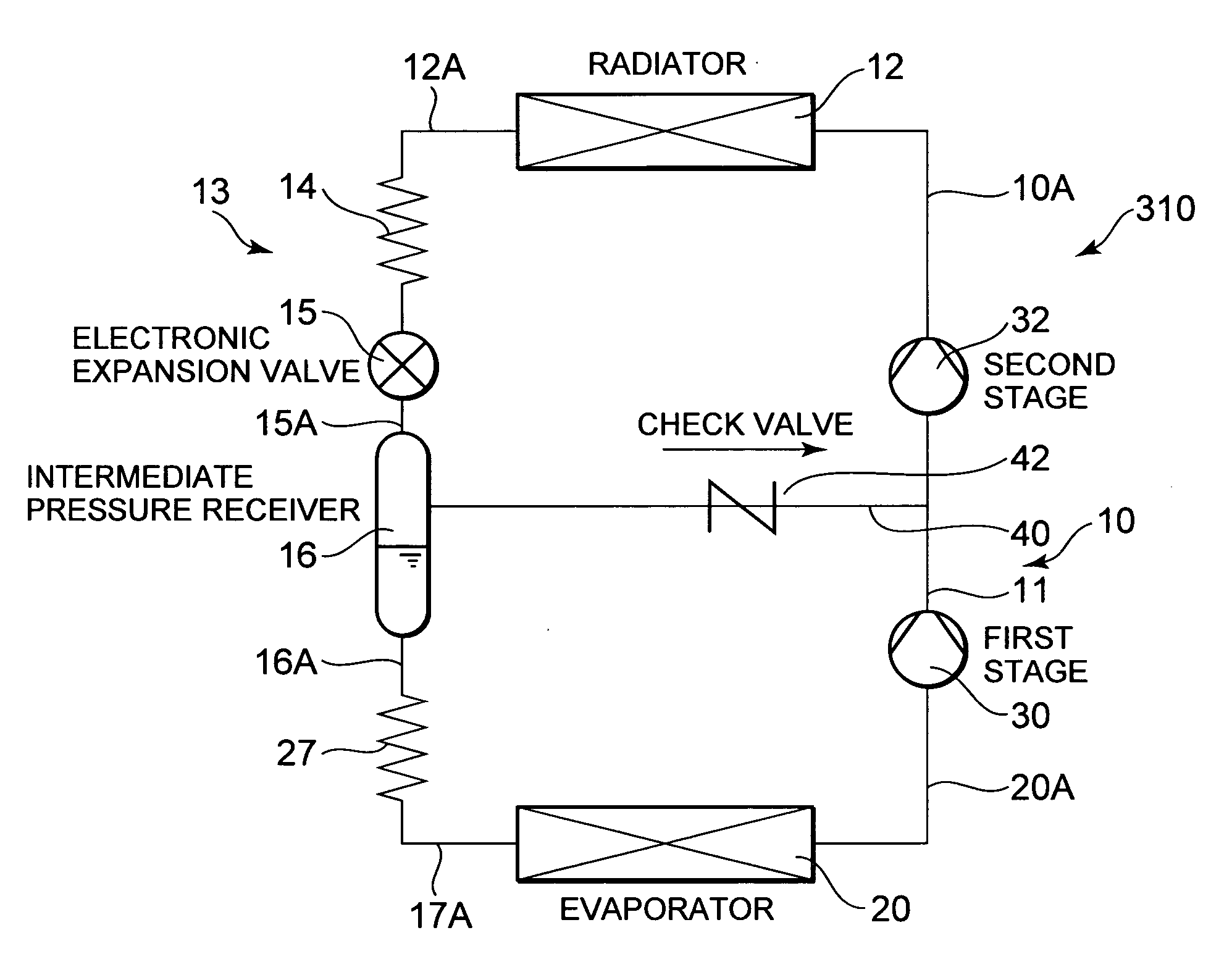
[0052] The present invention is not limited to the above-described embodiment in which a second pressure reducing device comprises an electronic expansion valve. For example, as shown in FIG. 4, the second pressure reducing device may comprise a conventional capillary tube.
[0053]FIG. 4 is a refrigerant circuit diagram of a refrigerant cycle apparatus 310 of the present embodiment. Reference numeral 27 denotes a capillary tube which is the second pressure reducing device. In FIG. 4, components denoted with the same reference numerals as those of FIGS. 1 and 3 produce identical or similar effects.
[0054] Even in the present embodiment, in the same manner as in the above-described embodiments, a refrigerant having a supercritical state is first pressure reduced by a capillary tube 14 having a small inner diameter, and accordingly the refrigerant can be sufficiently pressure reduced. Therefore, an appropriate control is possible by a usual electronic expansion valve 15 disposed on a do...
PUM
 Abstract
Description
Claims
Application Information
 - R&D
- Intellectual Property
- Life Sciences
- Materials
- Tech Scout
- Unparalleled Data Quality
- Higher Quality Content
- 60% Fewer Hallucinations
Browse by: Latest US Patents, China's latest patents, Technical Efficacy Thesaurus, Application Domain, Technology Topic, Popular Technical Reports.
© 2025 PatSnap. All rights reserved.Legal|Privacy policy|Modern Slavery Act Transparency Statement|Sitemap|About US| Contact US: help@patsnap.com


