

Luminescent material and light emitting diode using the same
a technology of light-emitting diodes and luminescent materials, which is applied in the direction of discharge tubes/lamp details, discharge tubes/lamp details, luminescent compositions, etc., can solve the problems of poor color rendition of conjugated aluminates, inability to optimally position excitation and emission bands of these aluminates, etc., to achieve high color rendering, efficient excitation of uv/blue radiation, and easy production
- Summary
- Abstract
- Description
- Claims
- Application Information
AI Technical Summary
Benefits of technology
Problems solved by technology
Method used
Image

Examples
Embodiment Construction
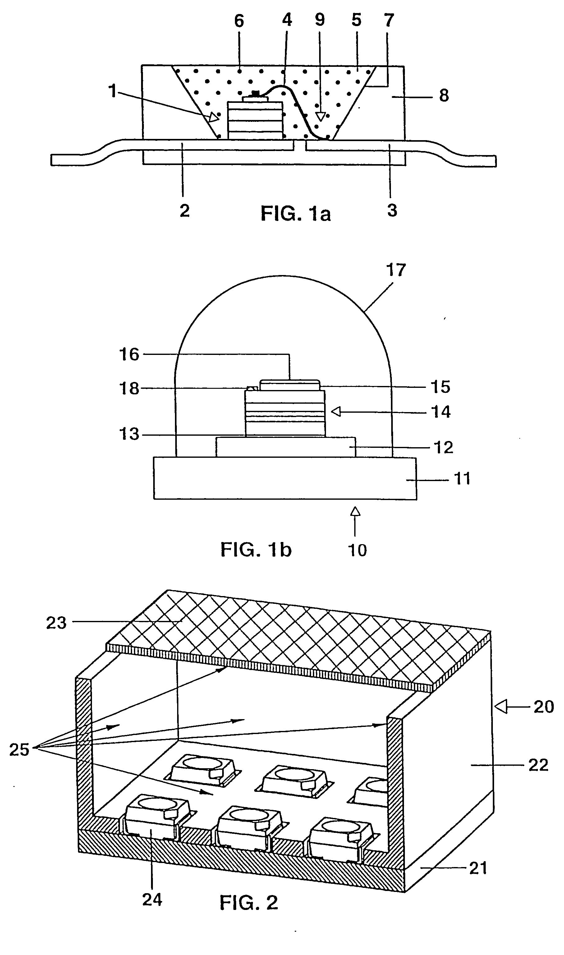
[0016] By way of example, a structure similar to that used in WO 01 / 40403 is described for use in a white LED together with an InGaN chip. The structure of such a light source for white light is specifically shown in FIG. 1a. The light source is based on a semiconductor component (chip 1) of type InGaN with a peak emission wavelength of 400 nm, having a first and a second electrical connection 2,3, which is embedded in an opaque base housing 8 in the region of a recess 9. One of the connections 3 is connected to the chip 1 via a bonding wire 4. The recess has a wall 7 which serves as reflector for the blue primary radiation of the chip 1. The recess 9 is filled with a potting compound 5 which contains a silicone casting resin (or epoxy casting resin) as its main constituents (pref. more than 80 by weight) and further comprises phosphor pigments 6 (pref. less than 15% by weight). There are also further small amounts of, inter alia, methyl ether and Aerosil. The phosphor pigments are ...
PUM
| Property | Measurement | Unit |
|---|---|---|
| peak emission wavelength | aaaaa | aaaaa |
| wavelengths | aaaaa | aaaaa |
| composition | aaaaa | aaaaa |
Abstract
Description
Claims
Application Information