Landfill design and method for improved landfill gas capture

a landfill gas and design method technology, applied in landfill technologies, applications, refuse collection, etc., can solve the problems of air intrusion almost always occurring, gas extraction rate from well b>3/b> may be too low, and achieve the effect of low gas permeability

Inactive Publication Date: 2006-02-16
INST FOR ENVIRONMENTAL MANAGEMENT
View PDF6 Cites 26 Cited by
  • Summary
  • Abstract
  • Description
  • Claims
  • Application Information

AI Technical Summary

Benefits of technology

[0015] The invention provides an improved method of collecting biogas from a landfill that allows biogas to be very efficiently collected while minimizing entrainment of air into the landfill and into the collected biogas. Landfill designs and modifications that facilitate the method are also disclosed.
[0016] The method involves providing the landfill with an upper gas containment layer near the surface of the landfill to retard biogas escape and air entrainment into the landfill. Underneath the gas containment layer (or closer to the landfill interior or center from the gas containment layer) is provided a gas-permeable conductive layer. Underneath the conductive layer (or, again, closer to the landfill waste mass center), a well withdraws biogas from the landfill. This system results in efficient capture of biogas from the landfill, with minimal air contamination of the biogas. Because the biogas passes from the gas-conductive layer through the waste mass to the well, the biogas collected from the well is consistent in its composition.
[0017] The method can be further improved by monitoring the gas composition of the gas-permeable conductive layer and adjusting the rate of biogas withdrawal from the well in response to the gas composition of the gas-permeable layer. Withdrawal of biogas from the well creates a partial vacuum that draws gas from the gas-permeable conductive layer down through the waste mass to the well. If the rate of gas withdrawal from the well is too rapid, air will be entrained from the atmosphere into the gas-permeable conductive layer. But if the rate of gas withdrawal from the well is too slow, biogas may percolate through the gas-containment layer and the surface of the landfill to escape. Monitoring the gas composition of the gas-permeable layer allows one to determine quickly and continuously whether the rate of gas withdrawal from the well is too fast or too slow and adjust the rate accordingly. If the gas-permeable layer has too much nitrogen or oxygen, too much air is being entrained into the gas-permeable layer, and the rate of biogas withdrawal from the well is too fast. But if the gas-permeable layer contains no nitrogen or oxygen, the rate of biogas withdrawal from the well may be too slow, and biogas may be escaping from the surface of the landfill.
[0020] Another embodiment of the invention provides a method of adapting a landfill for biogas collection, wherein the landfill has a surface contacting the atmosphere. The method involves first providing the landfill with a biogas-collection system comprising: (i) at or near the surface contacting the atmosphere a gas-containment layer that has low gas permeability; (ii) underneath the gas-containment layer and above most of the landfill mass a gas-permeable layer that has at least 10-fold the gas permeability of the gas-containment layer; and (iii) at least one gas-collection well that collects biogas from an extraction location beneath and separated by waste from the gas-permeable layer and draws it to the surface, the well comprising a biogas-collecting wellhead at the extraction location and a gas-impermeable conduit linking the wellhead to the surface to draw biogas from the wellhead to the surface. In operation of the system biogas collection through the gas-collection well generates an entrainment zone of the landfill beneath the gas-permeable layer, the entrainment zone defined as a 2-dimensional area immediately underneath the gas-permeable layer through which at least 30% of gas passing from the gas-permeable layer to the gas-collection well passes. The method involves second providing the landfill with a gas-impermeable geomembrane in or above the gas-containment layer and vertically overlaying most or all of the entrainment zone to prevent gas flow from the atmosphere above the entrainment zone.

Problems solved by technology

Air inevitably permeates most landfill containment, and air intrusion can almost always occur and has potential to be a problem.
If no air gases are detected in the gas-permeable layer, the gas extraction rate from the well 3 may be too low.

Method used


Image

  • Landfill design and method for improved landfill gas capture
  • Landfill design and method for improved landfill gas capture
  • Landfill design and method for improved landfill gas capture

Examples


example 2

Numerical Analysis of Gas Collection. A Calculation of Highly Conductive Layer Application and Performance for Gas Collection Effectiveness

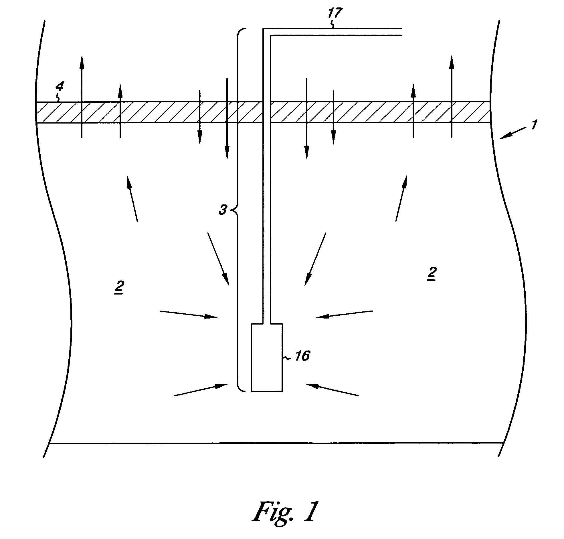
[0108] Definition of performance. Performance is defined here by two criteria: completeness of generated LFG collection, desirably over 90%, and limiting air entrainment, such that nitrogen from entrained atmospheric air is under 10% (and thus methane content over 50%, with LFG as generated at its “typical” 55% methane).

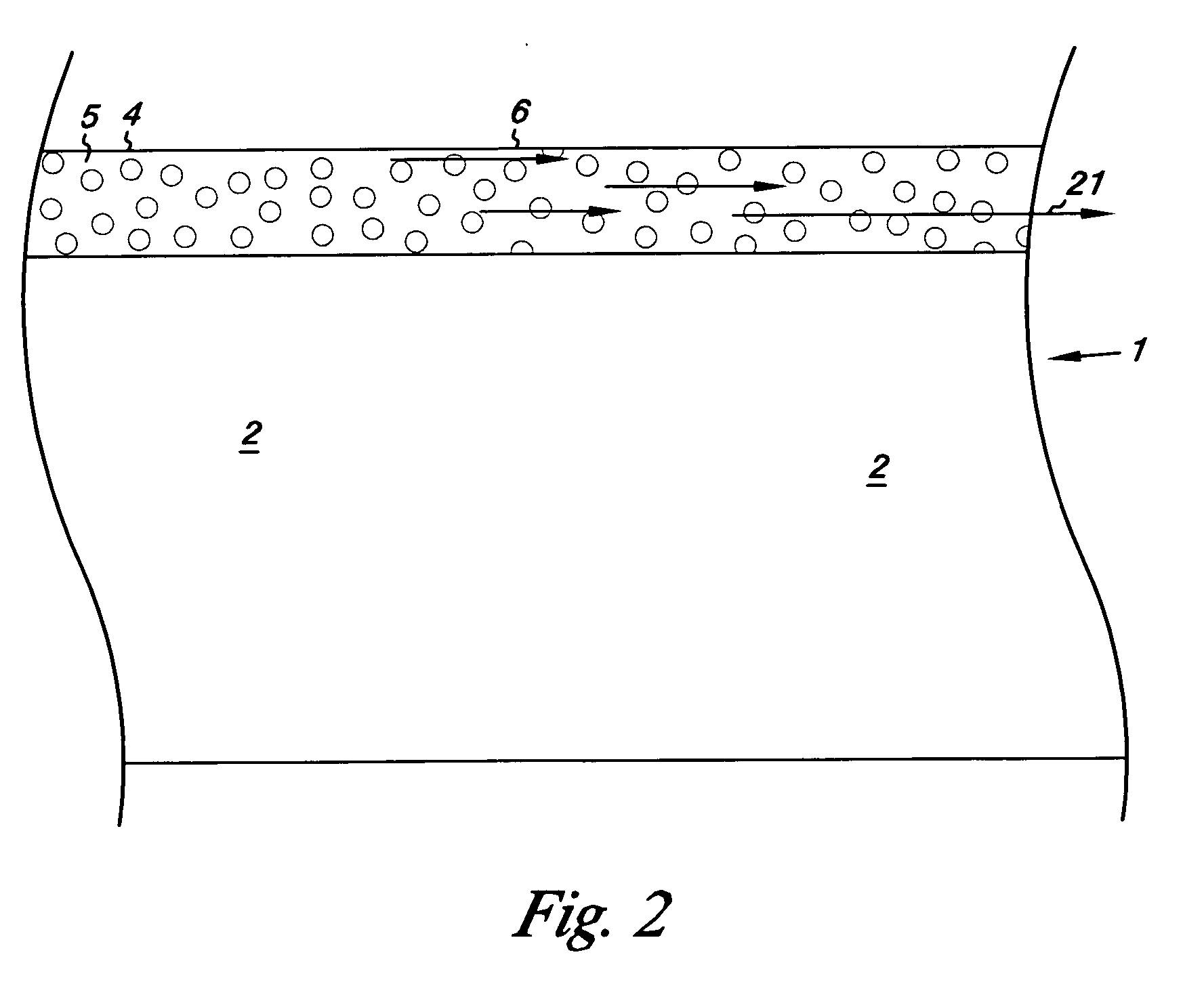
[0109] The following is an analysis of gas recovery using one example (of many possible) of the near-surface LFG-conducting (highly conductive) layer described in the preceding text. This example is chosen to be realistic and constructible. Parameters are chosen to be conservative. It is recognized that key parameters may actually range widely. Thus sensitivity of LFG recovery performance to changes in important parameters is discussed later.

[0110] Summary of LFG recovery performance. Finite element analysis indicates that the...


PUM


Abstract

The invention provides an improved method of collecting biogas from a landfill that results in more complete collection of biogas produced in the landfill, and with less contamination with air. The method involves providing the landfill with an upper gas containment layer near the surface of the landfill to retard biogas escape and air entrainment into the landfill. Underneath the gas containment layer is provided a gas-permeable conductive layer. Underneath the conductive layer, a well withdraws biogas from the landfill. Withdrawal of biogas from the well creates a partial vacuum that draws gas from the gas-permeable conductive layer down through the waste mass to the well. If the rate of gas withdrawal from the well is too rapid, air will be entrained from the atmosphere into the gas-permeable conductive layer. But if the rate of gas withdrawal from the well is too slow, biogas may percolate through the gas-containment layer and the surface of the landfill to escape. Monitoring the gas composition of the gas-permeable layer allows one to determine quickly and continuously whether the rate of gas withdrawal from the well is too fast or too slow.

Description

[0001] This application claims priority from U.S. provisional patent application Ser. No. 60 / 589,860, filed Jul. 22, 2004, “Landfill design and operational method for improved landfill gas capture,” which is incorporated by reference.BACKGROUND [0002] Landfilling and landfill gas. Landfilling and dumping dominate waste disposal in the United States, as well as waste disposal worldwide. The US EPA estimates US landfilling of Municipal Solid Waste (“MSW”) at about 160 million tons annually over the past few years (U.S. EPA 2002) And, worldwide, even greater tonnages of organic solid wastes, severalfold those of the US, are landfilled and otherwise buried in dumps around the world [0003] In wastes either buried in landfills or simply dumped, organic components decompose to form “landfill gas” (LFG) or biogas. LFG (biogas) comprises approximately equal volumes of methane and carbon dioxide, with lesser amounts of other gases and moderate levels of pollutants. A representative reaction f...

Claims


Application Information

Patent Timeline
Patent Type & Authority Applications(United States)
IPC IPC(8): G21F5/00B09B1/00
CPCB09B1/00B09B1/004Y02E50/343Y02C20/20B09B1/006Y02E50/30Y02W30/30
Inventor AUGENSTEIN, DON CHURCHILLBENEMANN, JOHN RUDIGERYAZDANI, RAMIN
Owner INST FOR ENVIRONMENTAL MANAGEMENT
Why Eureka
Try Eureka