
Die for forming honeycomb structure and method of manufacturing the same

a technology of honeycomb and die, which is applied in the direction of dough shaping, manufacturing tools, applications, etc., can solve the problems of affecting the shape of the extruded honeycomb, the slits are worn, and the extruded honeycomb article gradually changes its shape, so as to achieve superior wear resistance and high formability.

Active Publication Date: 2006-02-16
NGK INSULATORS LTD
View PDF10 Cites 39 Cited by
  • Summary
  • Abstract
  • Description
  • Claims
  • Application Information

AI Technical Summary

Benefits of technology

The present invention provides a die for forming a honeycomb structure that has high formability and resistance to wear. The die has slits of a honeycomb shape in one surface and back holes that introduce a forming material therethrough in the other surface. The die is made by stacking and bonding two plate-like members together. The die base has high tensile and compressive stresses in the bonded surface. The invention also provides a method of manufacturing the die and a re-thermal treatment for the die. The technical effects of the invention are improved formability and resistance to wear of the die, as well as improved manufacturing efficiency and accuracy.

Problems solved by technology

However, as to the die base using a stainless steel or the like, since a resistance to wear of the substrate is low, there has been a problem that slits are worn by continuous extrusion, and a shape of an extruded honeycomb article gradually changes.
Conversely, when the back holes little influenced by the wear or the like are disposed, there is a problem that much labor and time are required.
Since the super hard alloy is a brittle material, there is a problem that the die is broken by a pressure at an extruding time.
In this case, even if the slit is disposed which corresponds to the width of the partition wall of the honeycomb structure to be extruded, there has been a problem that the width of the slit is deformed after machining, and the honeycomb structure having a predetermined shape cannot be extruded because of the presence of a large residual stress.
There has also been a problem that the super hard alloy is easily cracked, and a working tool such as an abrasive wheel is easily broken during the machining of the die base (die precursor).

Method used


Image

  • Die for forming honeycomb structure and method of manufacturing the same
  • Die for forming honeycomb structure and method of manufacturing the same
  • Die for forming honeycomb structure and method of manufacturing the same

Examples


example 1

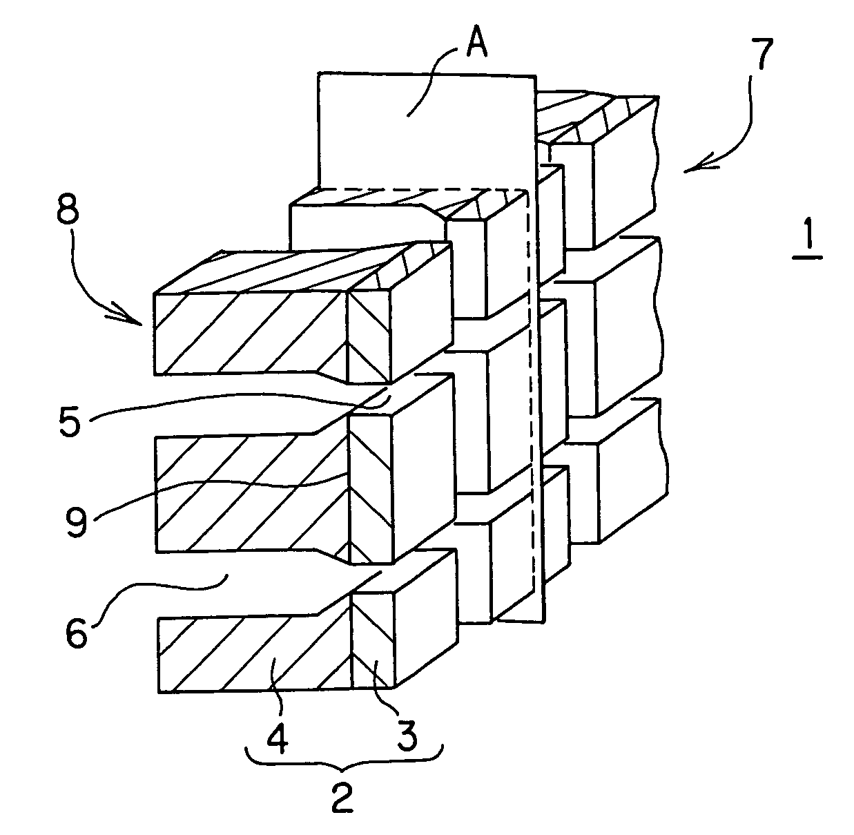
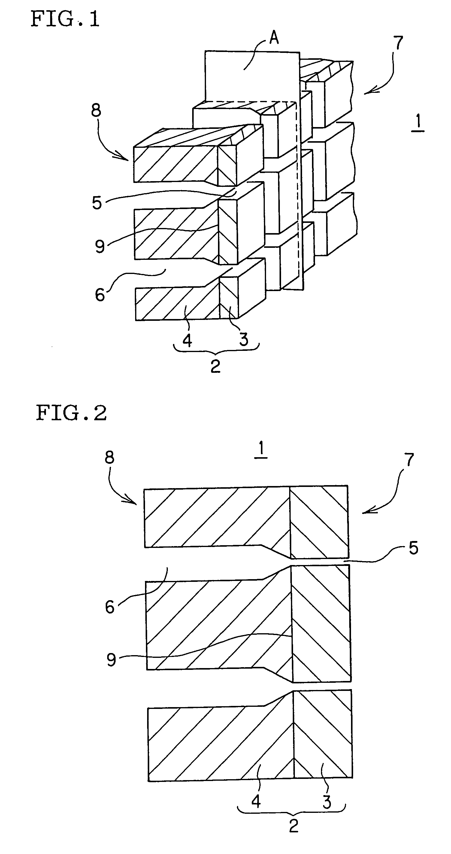
[0068] A die for forming a honeycomb structure was manufactured, comprising: a die base having two surfaces. One of the surfaces was provided with slits of a honeycomb shape, the other surface was provided with back holes which communicated with the slits and introduced a forming material therethrough, and the forming material introduced into the back holes was extruded from the slits to form the honeycomb structure. In the die for forming the honeycomb structure of Example 1, a die precursor constituting the die base was used, which was obtained by stacking and bonding a first member made of a super hard alloy of WC-16 mass % Co, and a second member made of SUS630 (C; 0.07 or less, Si; 1.00 or less, Mn; 1.00 or less, P; 0.040 or less, S; 0.030 or less, Ni; 3.00 to 5.00, Cr; 15.50 to 17.50, Cu; 3.00 to 5.00, Nb+Ta; 0.15 to 0.45, Fe; balance (unit was mass %) together in such a manner that tensile and compressive stresses in a mutually bonded surface were 500 MPa.

[0069] It is to be ...


PUM

PropertyMeasurementUnit
compressive stressesaaaaaaaaaa
widthaaaaaaaaaa

Abstract

There is disclosed a die for forming a honeycomb structure, which realizes a sophisticated formability and which is superior in resistance to wear. A die for forming the honeycomb structure is provided with a die base having two surfaces, one surface is provided with slits of a honeycomb shape, and the other surface is provided with back holes which introduce a forming material therethrough. This die base includes: a die precursor which is obtained by stacking and bonding a first member which is one surface of the die base and is made of a tungsten carbide-based super hard alloy containing at least tungsten carbide, and a second member which is the other surface of the die base and is made of a metal material capable of causing at least one of three phase transformations of martensite transformation, bainite transformation, and pearlite transformation by cooling of an austenite phase together. Tensile and compressive stresses in a mutually bonded surface of the two plate-like members are 1000 MPa or less.

Description

BACKGROUND OF THE INVENTION [0001] 1. Field of the Invention [0002] The present invention relates to a die for forming a honeycomb structure, and a method of manufacturing the die. The present invention particularly relates to a die for forming a honeycomb structure, which realizes a high formability and which has an excellent resistance to wear, and a method of manufacturing the die. [0003] 2. Description of the Related Art [0004] As a method of forming a honeycomb structure made of a ceramic, a method has heretofore been performed broadly in which a forming material (clay) is extruded using a die for forming the honeycomb structure. The die comprises a die base provided with back holes for introducing the material therethrough, and slits of a lattice shape which communicate with the back holes. As to this die, usually in one surface of the die base, slits having widths corresponding to partition wall thicknesses of the honeycomb structure are arranged in the lattice shape or the l...

Claims


Application Information

Patent Timeline
Patent Type & Authority Applications(United States)
IPC IPC(8): B29C47/12B29C48/30B29C48/11B29C48/32
CPCB29C47/0028B29L2031/60B29C47/12B29C47/0852B28B3/269B29C48/11B29C48/3003
Inventor TAKAHASHI, HIRONORIHOSOKAWA, HIROFUMIKONDO, YOSHIMASAHIRONAGA, MASAYUKI
Owner NGK INSULATORS LTD
Learn More