METHOD for AUTO-REGULATING FAN SPEED

a technology of fan speed and auto-regulation, which is applied in the field of auto-regulating the speed of the fan, can solve the problems of easy over-heating of the operating temperature inside the system, insufficient heat conductivity of the ic chip, and easy over-heating of the air steam, so as to prevent any damage due to an excessive rise in the temperature of the thermal source, the effect of increasing the cooling rate of the fan

Inactive Publication Date: 2006-02-23
COMPAL ELECTRONICS INC
View PDF3 Cites 30 Cited by
  • Summary
  • Abstract
  • Description
  • Claims
  • Application Information

AI Technical Summary

Benefits of technology

[0009] Accordingly, at least one objective of the present invention is to provide a method that utilizes a feedback control mechanism to regulate the fan speed of

Problems solved by technology

In most notebook or other computer systems, it is insufficient to conduct the heat generated from the IC chips by only using the heat sink.
Furthermore, the air steam may produce a phenomenon of local high temperature close to the air outlet after absorbing a large quantity of heat from the operating ICs.
When the air inlet or the air outlet is blocked causing a poor air circulation, the operating temperature inside the system easily becomes over high, causing an occurrence of damage.
Once the temperature of internal IC chips or other internal devices exceed the specified operating range, computational error or temporary failure of the system may occur in the main board.
However, if the system does not have a mechanism for detecting the difference between the actual fan speed of the fan and a prescribed fan speed but provi

Method used


Image

  • METHOD for AUTO-REGULATING FAN SPEED
  • METHOD for AUTO-REGULATING FAN SPEED
  • METHOD for AUTO-REGULATING FAN SPEED

Examples


Embodiment Construction

[0025] Reference will now be made in detail to the present preferred embodiments of the invention, examples of which are illustrated in the accompanying drawings. Wherever possible, the same reference numbers are used in the drawings and the description to refer to the same or like parts.

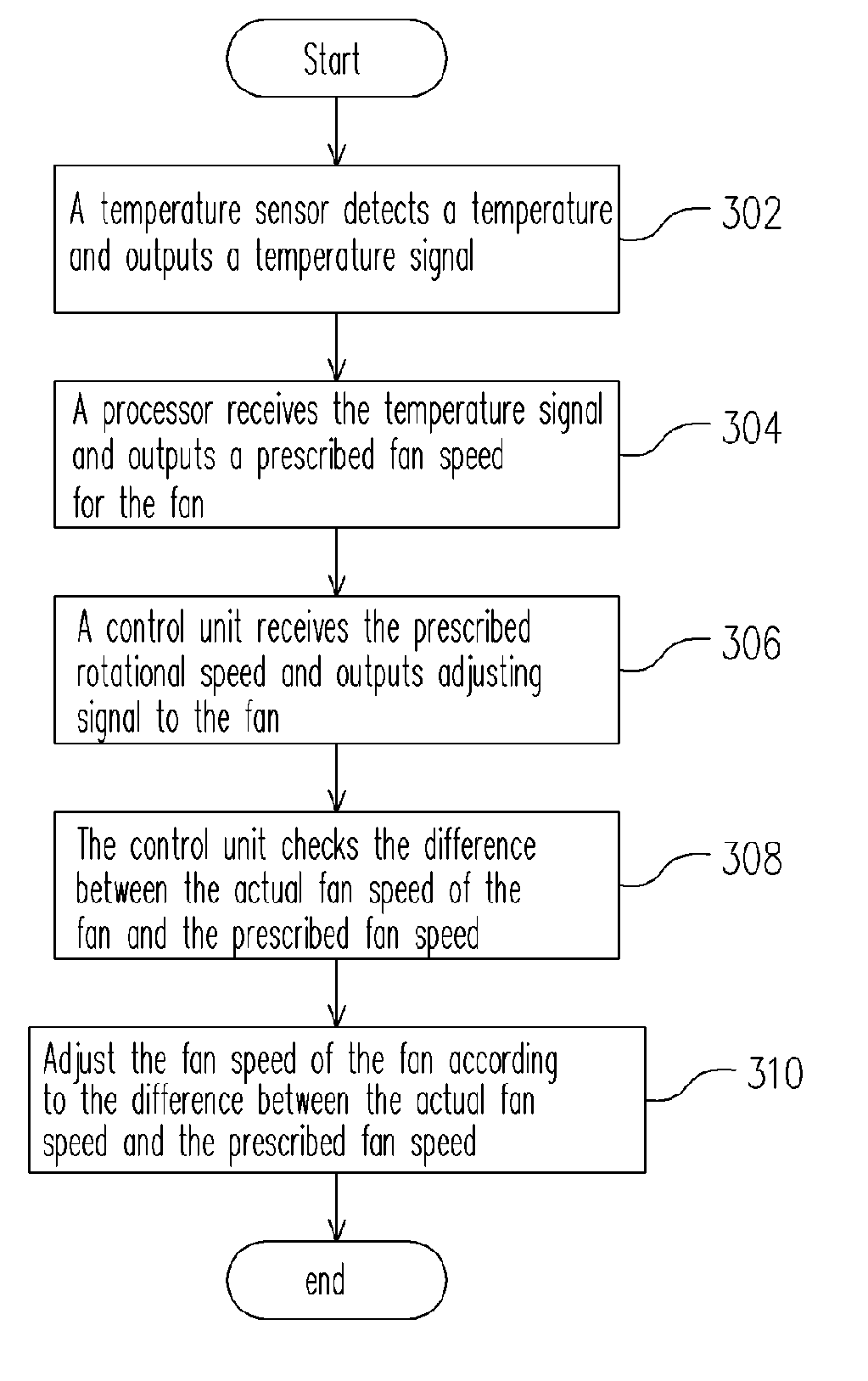
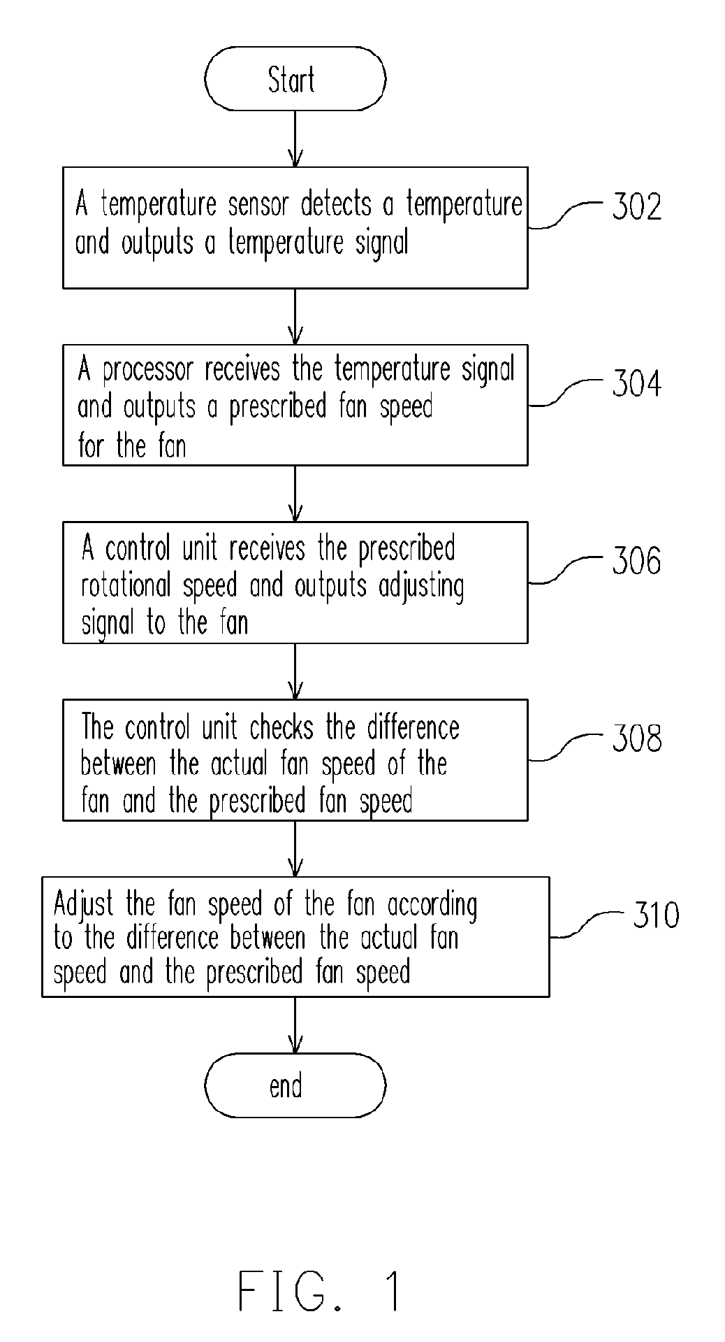
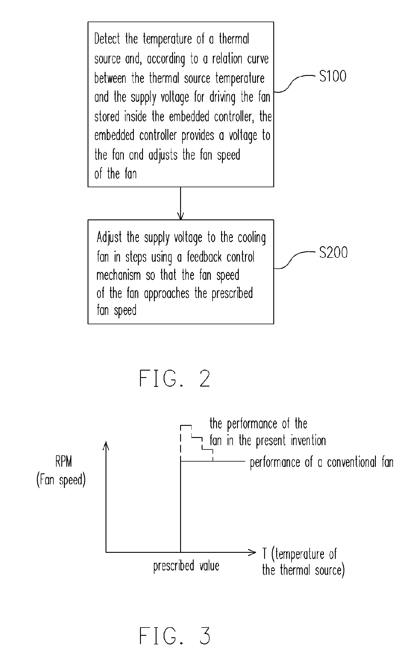
[0026]FIG. 2 is a flow chart showing the steps for auto-regulating the fan speed of a cooling fan according to one preferred embodiment of the present invention. As shown in FIG. 2, the method for auto-regulating the fan speed of the cooling fan comprises the following steps. In step S100, the temperature of a thermal source is detected. Thereafter, according to a curve relating the temperature of the thermal source with the voltage for driving the fan stored inside an embedded controller, the embedded controller provides a corresponding voltage to the fan to adjust the fan speed. In step S200, a feedback control mechanism is utilized to adjust the supply voltage to the fan in steps so that the fan...


PUM


Abstract

The present invention relates to a method for auto-regulating the fan speed. The method includes detecting the temperature of a thermal source. When the temperature of the thermal source exceeds a target value, the fan speed of the fan is regulated according to a relation between the temperature of the thermal source and the fan speed of the fan. Thereafter, the voltage applied to the fan is micro-adjusted through a feedback control mechanism so that the fan speed of the fan reaches a specified speed in steps.

Description

CROSS-REFERENCE TO RELATED APPLICATION [0001] This application claims the priority benefit of Taiwan application serial no. 93124620, filed Aug. 17, 2004. BACKGROUND OF THE INVENTION [0002] 1. Field of the Invention [0003] The present invention relates to a method of regulating a cooling fan. More particularly, the present invention relates to a method for regulating the fan speed automatically so that the cooling performance is increased and a balance between the cooling efficiency and the noise of the cooling fan is achieved. [0004] 2. Description of the Related Art [0005] A conventional cooling system is normally categorized into an air-cooling type and a water-cooling type. Using a notebook computer as an example, all of the central processor, the north bridge chip and the graphic chip on a main board are integrated circuit (IC) chips. In general, integrated circuit (IC) chips are the major sources of heat during operations in computer. To rapidly carry the heat generated by the...

Claims


Application Information

Patent Timeline
IPC IPC(8): F25B21/02F24F7/00F25D17/00
CPCG06F1/206H01L23/34H01L23/467H05K7/20209H01L2924/0002H01L2924/00
Inventor TIEN, CHI-WEIPAN, JENQ-HAUR
Owner COMPAL ELECTRONICS INC
Why Eureka
Try Eureka