Multi-stage turbocharging system with efficient bypass

a turbocharging system and multi-stage technology, applied in the direction of machines/engines, stators, mechanical equipment, etc., can solve the problems of unnecessary loss of useful energy, reduce the efficiency of internal combustion engine systems, and reduce the amount of energy. , to achieve the effect of saving energy, and preserving, capturing, utilizing and/or reducing the amount of energy

Inactive Publication Date: 2006-03-02
ENVIRONMENTAL PROTECTION AGENCY US
View PDF9 Cites 78 Cited by
  • Summary
  • Abstract
  • Description
  • Claims
  • Application Information

AI Technical Summary

Benefits of technology

[0009] In furtherance of the object of this invention, it has been recognized that prior art wastegate and bypass mechanisms are a source of unnecessary loss of useful energy in prior art multi-stage turbocharging systems. Therefore, a further object of the present invention is to provide an efficient means for preserving, capturing, utilizing, and/or reducing the amount of energy otherwise lost in bypassing between stages in multi-stage turbocharging systems, in order to further improve the efficiency of internal combustion engine systems utilizing multi-stage turbocharging systems.
[0010] The present invention reduces the unrecovered loss of exhaust gas energy that otherwise occurs in bypassing exhaust flow from one stage to another in a conventional multi-stage turbocharging system. The preferred method of preserving such exhaust energy is through converting a portion of the exhaust energy of the bypassed flow from pressure to velocity by passing the bypassed flow, while substantially still at the higher exhaust energy level present upstream of the bypassed turbine, through a variable geometry valve/nozzle, turbine VGT va

Problems solved by technology

In a turbocharged internal combustion engine system, the wide range of speed and power output levels at which the internal combustion engine may o

Method used


Image

  • Multi-stage turbocharging system with efficient bypass
  • Multi-stage turbocharging system with efficient bypass
  • Multi-stage turbocharging system with efficient bypass

Examples


Embodiment Construction

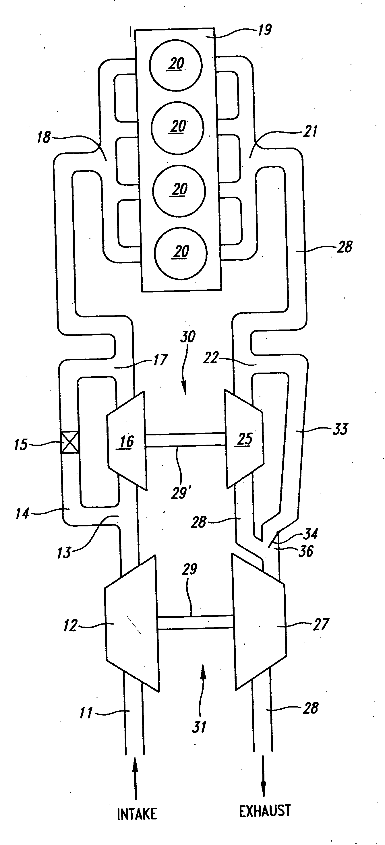
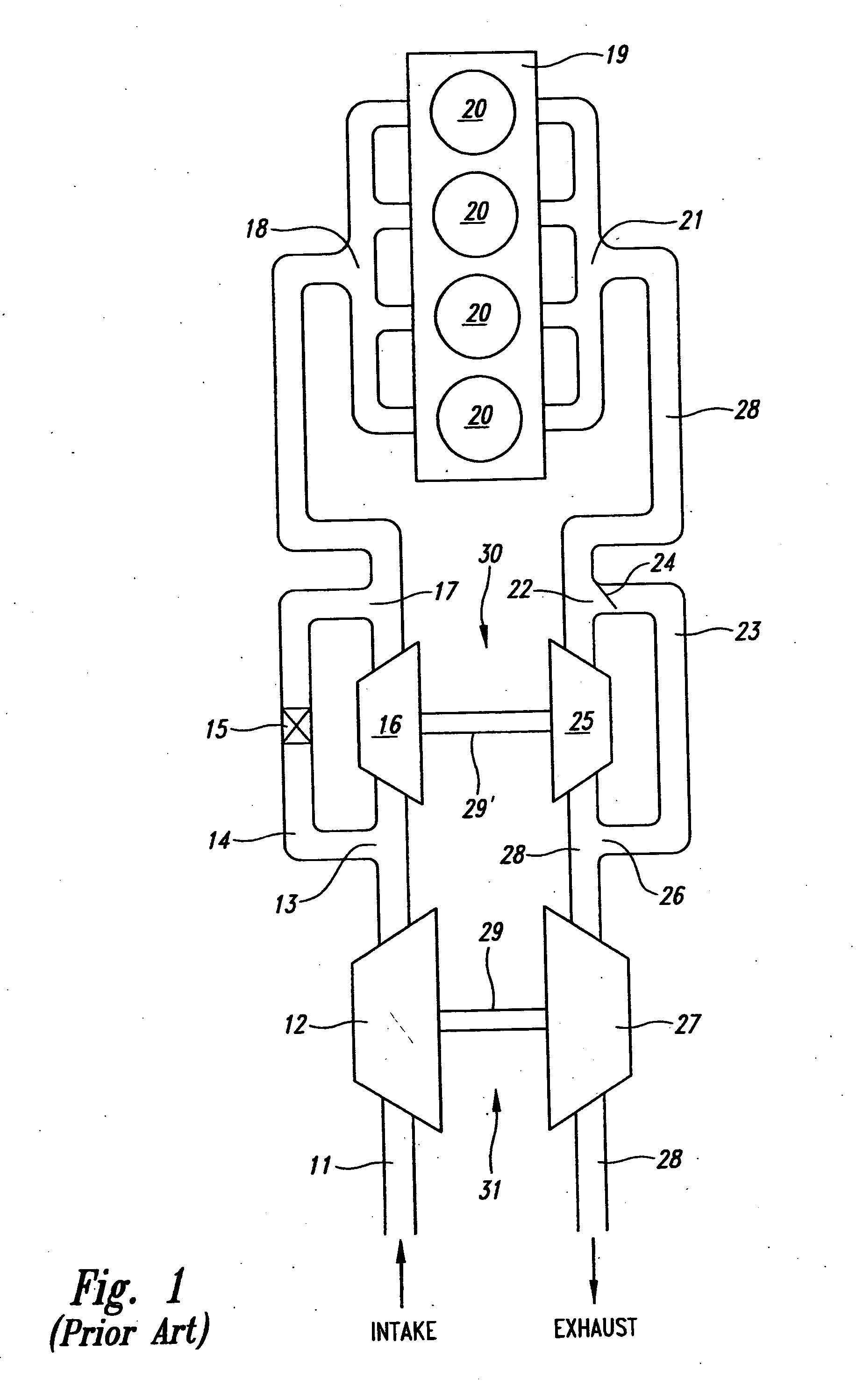
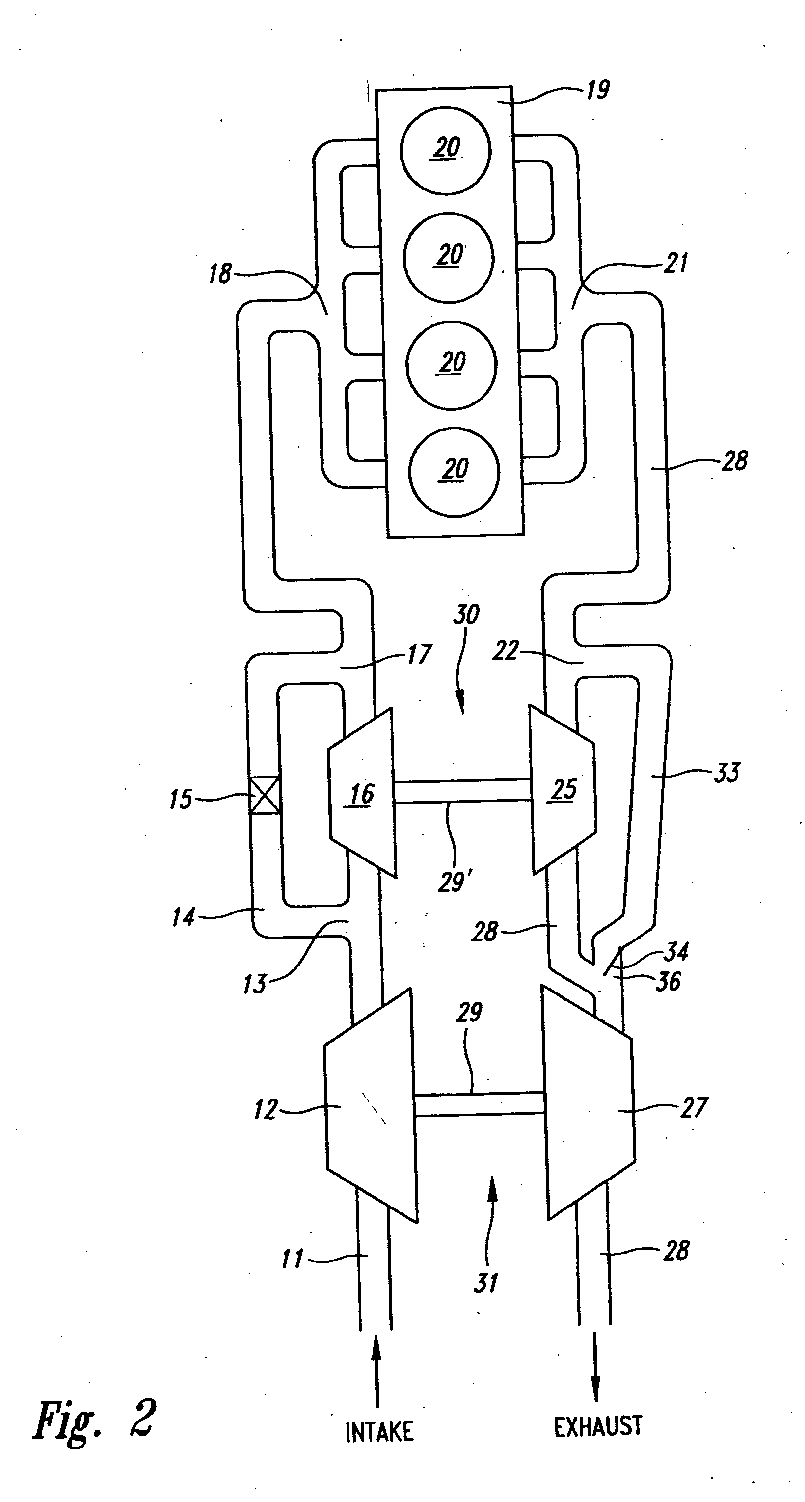
[0028]FIG. 1 shows an internal combustion engine system with a multi-stage turbocharging and bypass system from the prior art. Referring to FIG. 1, ambient air enters the system through intake line 11. The intake air may optionally be mixed with recirculated exhaust gas (EGR) to form a charge-air mixture. The ambient air or EGR / ambient air mixture (“charge-air”) mixture flows through and is compressed by a first-stage low pressure air compressor 12.

[0029] After compression in compressor 12, the intake air may flow through a second-stage high pressure air compressor 16 for further compression. Alternatively, the intake air may be diverted at port 13 to optional bypass channel 14 and return to the intake line at port 17, as regulated by the opening or closing of optional bypass valve 15.

[0030] Intake air then enters the intake manifold 18 and into combustion chambers 20 of engine 19 through conventional valves (not shown) in a conventional manner. Following combustion in the combust...


PUM


Abstract

A more efficient multi-stage turbocharging system and method for internal combustion engine systems is set forth. The present invention recovers the loss of a portion of exhaust energy that conventionally occurs in bypassing exhaust flow from one stage to another in a multi-stage turbocharging system. The preferred method of preserving such exhaust energy is through converting a portion of the exhaust energy of the bypassed flow from pressure to kinetic energy (velocity) by passing the bypassed flow through a VGT vane outlet or other variable geometry valve/nozzle, and then not allowing the accelerated flow to dissipate energy before reaching the subsequent stage's turbine wheel, where the accelerated flow may then be converted to a mechanical rotational force by the lower pressure turbine's wheel. Preferred hardware for achieving the object of the invention is also set forth, including a preferred two-volute low pressure turbocharging system with a VGT mechanism in one turbine volute only, or an alternative low pressure turbocharger with two low pressure turbines on a common shaft (again, preferably, with a VGT mechanism in one turbine only).

Description

CROSS-REFERENCE TO RELATED APPLICATION [0001] This application claims the priority benefit under 35 U.S.C. 119(e) of U.S. Provisional Patent Application No. 60 / 605,898, filed Aug. 31, 2004, which application is incorporated herein by reference in its entirety.BACKGROUND OF THE INVENTION [0002] 1. Field of the Invention [0003] This invention relates to internal combustion engine systems with multi-stage turbocharging systems, and the use of multi-stage turbines in general. [0004] 2. Description of the Related Art [0005] Turbocharging systems, such as for use with internal combustion engines, are well-known in the art. A turbocharger comprises an exhaust gas turbine coupled to a gas intake charge compressor. The turbine operates by receiving exhaust gas from an internal combustion engine and converting a portion of the energy in that exhaust gas stream into mechanical energy by passing the exhaust stream over blades of a turbine wheel, and thereby causing the turbine wheel to rotate. ...

Claims


Application Information

Patent Timeline
IPC IPC(8): F02D23/00F02B33/44
CPCF01D9/026F05D2220/40F01D17/143F01D17/146F01D17/165F02B29/083F02B37/001F02B37/004F02B37/013F02B37/025F02B37/18F02B37/183F02B37/22F02C3/13F02C6/12F02D9/06F02M25/0711F02M25/0713F02M25/0727Y02T10/121Y02T10/146Y02T10/144F01D17/141F02M26/08F02M26/10F02M26/23Y02T10/12F02B37/00F02D23/00
Inventor HAUGEN, DAVID JAMES
Owner ENVIRONMENTAL PROTECTION AGENCY US
Why Eureka
Try Eureka