Pattern cutter, its processing methods and moulds

a cutter and pattern technology, applied in the field of pattern cutters, can solve the problems of poor design consistency, low production efficiency, and unsuitability for mass production

Inactive Publication Date: 2006-03-02
DENG YEQING +1
View PDF99 Cites 9 Cited by
  • Summary
  • Abstract
  • Description
  • Claims
  • Application Information

AI Technical Summary

Problems solved by technology

But, the production efficiency is relatively low by using traditional hand paper-cutting method to make paper-cutting patterns, with a poor consistency in designs, hence it is not suitable for mass production.
The existing method to form such blades is generally to bend them by hand, leading to extremely low production efficiency and poor processing accuracy.
But, the technological process, through which the cutting blades are firstly machined and then assembled to a pattern cutter, will inevitably increase the processing and assembling steps, thereby the required materials and labor cost are still relatively high.

Method used


Image

  • Pattern cutter, its processing methods and moulds
  • Pattern cutter, its processing methods and moulds
  • Pattern cutter, its processing methods and moulds

Examples


working example 1

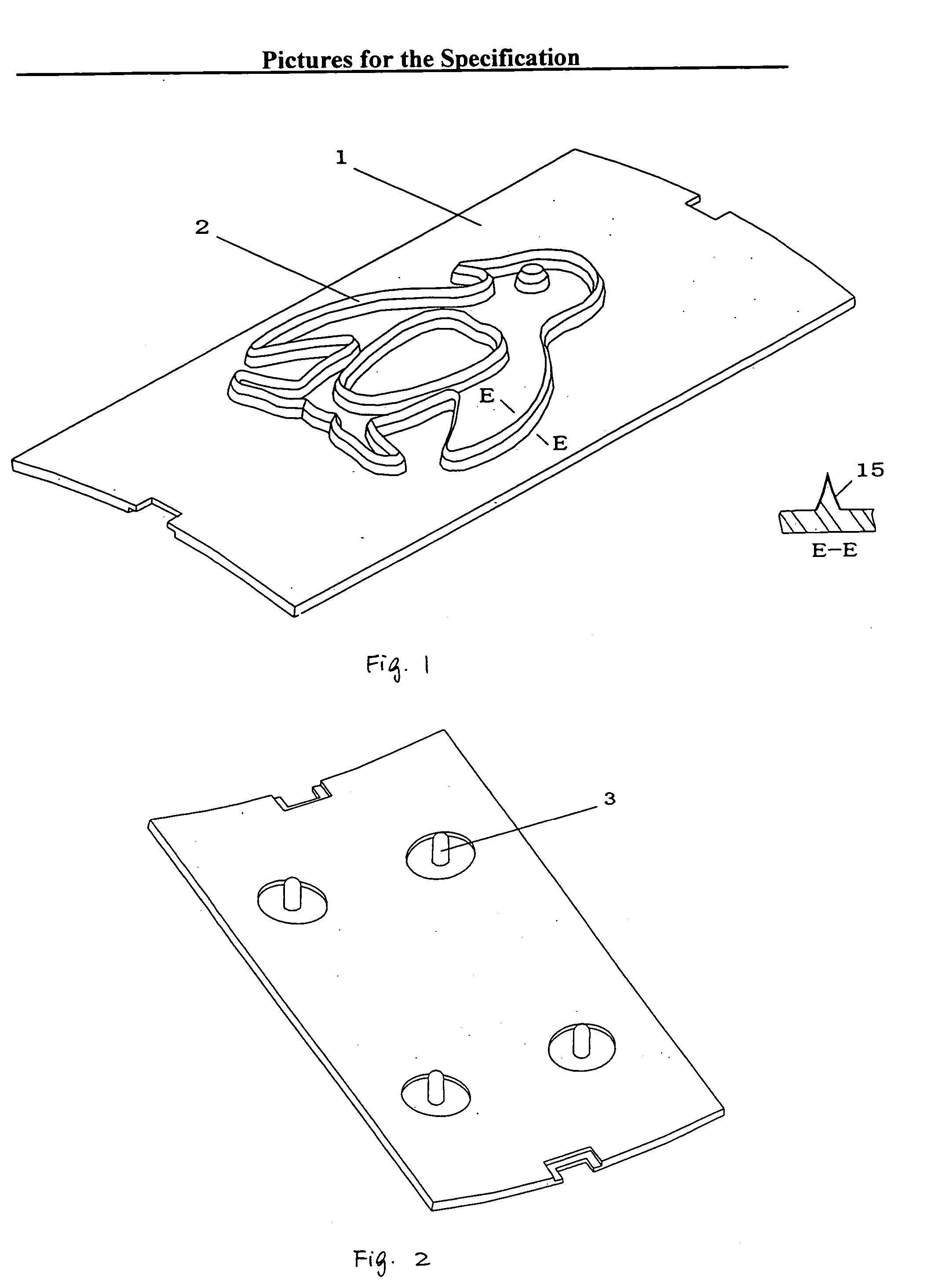
[0026]FIG. 1 and FIG. 2 show the concrete construction of the pattern cutter of the present invention. As shown in FIG. 1, the pattern cutter is composed of the base 1 and cutting blade 2. The base 1 is an arc plate with a certain radian. The cutting blade 2 is located on the base 1, with the surface of its cutting edge being in parallel to that of base 1 (both being of arc curved surface). The cutting blade 2 forms a penguin pattern shape to be cut. The said base 1 and cutting blade 2 are of one-piece construction. The specific cross sectional structure is shown in E-E view of FIG. 1. The cutting blade 2 has a cross sectional shape similar to triangle (the exact shape is the combination of triangle and trapezoid). The height of cutting blade 2 is 3 mm on the base 1. The cutting blade 2 has an angle of 30° at the cutting edge. On the surface of cutting blade 2 there is a plating coat 15. The holding legs 3 are integrally made on the said base 1 at the other side opposite to the surf...

working example 2

[0028]FIG. 6 shows another construction of the pattern cutter as set forth in the present invention. As shown in FIG. 6, this pattern cutter comprises a base 1 and cutting blade 2. The base 1 is a flat plate, with the cutting blade 2 located on the base 1. The surface for the cutting edge of the blade is in parallel to that of the base 1 (both of them being of plane). The cutting blade 2 forms the circular pattern shape that is to be cut. The said base 1 and the cutting blade 2 are of one-piece structure. The specific cross sectional structure is as shown in G-G view of FIG. 6. The cross sectional shape of the cutting blade 2 is of triangle. The height of the cutting blade 2 is 4 mm on the base 1. The blade 2 has an angle of 40° at the cutting edge. The cutting blade 2 is surfaced with a chromium-plating coat 15.

[0029] The methods for manufacturing the pattern cutter as set forth in the present working example are the same as those in the working example 1 in addition to the follow...


PUM

PropertyMeasurementUnit
heightaaaaaaaaaa
included angleaaaaaaaaaa
depthaaaaaaaaaa

Abstract

Disclosed here in the present invention is a pattern cutter, including a base and cutting blade. The cutting blade is located on the base. The blade forms the shape of pattern to be cut. The said base and cutting blade are of one-piece structure, which is machined to shape at one go through die-casting process. A method for processing such a pattern cutter, which directly utilizes mould to die cast the base and blade that are joined together. The said cutting blade forms the pattern shape that requires to be cut. A mould that is applied to the aforesaid processing method, inside the mould there is arranged a cavity for blade forming purpose. The said blade-forming cavity is of triangle or combination of triangle and rectangle or combination of triangle and trapezoid. The depth of blade-forming cavity is greater than or equal to 2.5 mm. The included angle at the sharp end of the blade-forming cavity is smaller than or equal to 60°. The present invention is characterized by simple and rational construction, easy to manufacture, low cost, high product accuracy and good consistency, with a wide range of adaptability and better market prospect.

Description

TECHNICAL FIELD [0001] The present invention relates to the pattern cutting technique and, more particularly, to a pattern cutter, its processing methods and moulds. BACKGROUND ART [0002] The traditional paper-cutting handicrafts are a kind of work of art gaining immense popular favor. With a large variety of designs or patterns and high value of artistic appreciation, the paper-cutting handicrafts are very suitable to the kindergarten education of children. Abroad, these kind of paper-cutting products are widely used for children education. In the United States, for example, the paper-cutting products are very popularized. The paper, plastic pieces, rubber pieces or similar materials are generally cut into letters, cartoon, animals or human-shaped patterns for cultivation of children's cognitive ability and discrimination. But, the production efficiency is relatively low by using traditional hand paper-cutting method to make paper-cutting patterns, with a poor consistency in design...

Claims


Application Information

Patent Timeline
Patent Type & Authority Applications(United States)
IPC IPC(8): B21K5/20B22D17/22B23P15/40B26D5/10B26D7/26B26F1/44B44B11/00
CPCB22D17/22B23P15/406B26D5/10B26F2001/4436B26D2007/2607B26F1/44B26D7/2614
Inventor DENG, YEQINGANGEVINE, FAYE
Owner DENG YEQING
Why Eureka
Try Eureka