Wired circuit board

a wired circuit board and wire technology, applied in the direction of printed circuit aspects, printed circuit manufacturing, electrical apparatus construction details, etc., can solve the problems of preventing the occurrence of insulating failure, etc., to suppress insulating failure, prevent short circuit from ionic migration, and improve adhesion

Inactive Publication Date: 2006-03-02
NITTO DENKO CORP
View PDF7 Cites 3 Cited by
  • Summary
  • Abstract
  • Description
  • Claims
  • Application Information

AI Technical Summary

Benefits of technology

[0011] It is an object of the invention to provide a wired circuit board which even when a conductive pattern is formed in the form of fine pitch can provide improved adhesion between the conductive pattern and an insulating layer to prevent a plating solution from remaining between metal plating layers and the insulating layer, so as to prevent ionic impurities in the plating solution from remaining as residual or ionic contamination, whereby even when electric current flows through the circuit under a high temperature and high humidity environment over a long term, a short circuit from ionic migration can be prevented to suppress insulating failure.
[0014] According to the wired circuit board of the present invention, the terminal portions and the metal plating layers are both partly embedded in the insulating layer. This constituent can provide the result that even when the conductive pattern is formed in the form of fine pitch, improved adhesion can be provided between the conductive pattern and the insulating layer to prevent infiltration of a plating solution into an interface between the metal plating layers and the insulating layer when the metal plating layer is formed. This can provide the result of preventing the ionic impurities in the plating solution from remaining as residual or ionic contamination in between the metal plating layers and the insulating layer. As a result, even when electric current flows through the circuit under a high temperature and high humidity environment over a long term, a short circuit from ionic migration can be prevented to suppress insulating failure.

Problems solved by technology

However, in this wired circuit board, there is the possibility when the metal plating layer is formed, a plating solution may infiltrate in an interface between the metal plating layer and the insulating base layer and remain therein, so that ionic impurities in the plating solution, such as chloride ion, may remain as a residual or ionic contamination.
When electric current flows through the circuit under a high temperature and high humidity environment over a long term in the state of such a residual remaining, a short circuit may occur from ionic migration, then leading to insulating failure.
The method disclosed by JP Laid-open (Unexamined) Patent Publication No. 2004-179341 as cited above may provide improved adhesion between the insulating base layer and the conductive pattern, but suffers from difficulties in preventing occurrence of the short circuit from the ionic migration.

Method used


Image

  • Wired circuit board
  • Wired circuit board
  • Wired circuit board

Examples


example 1

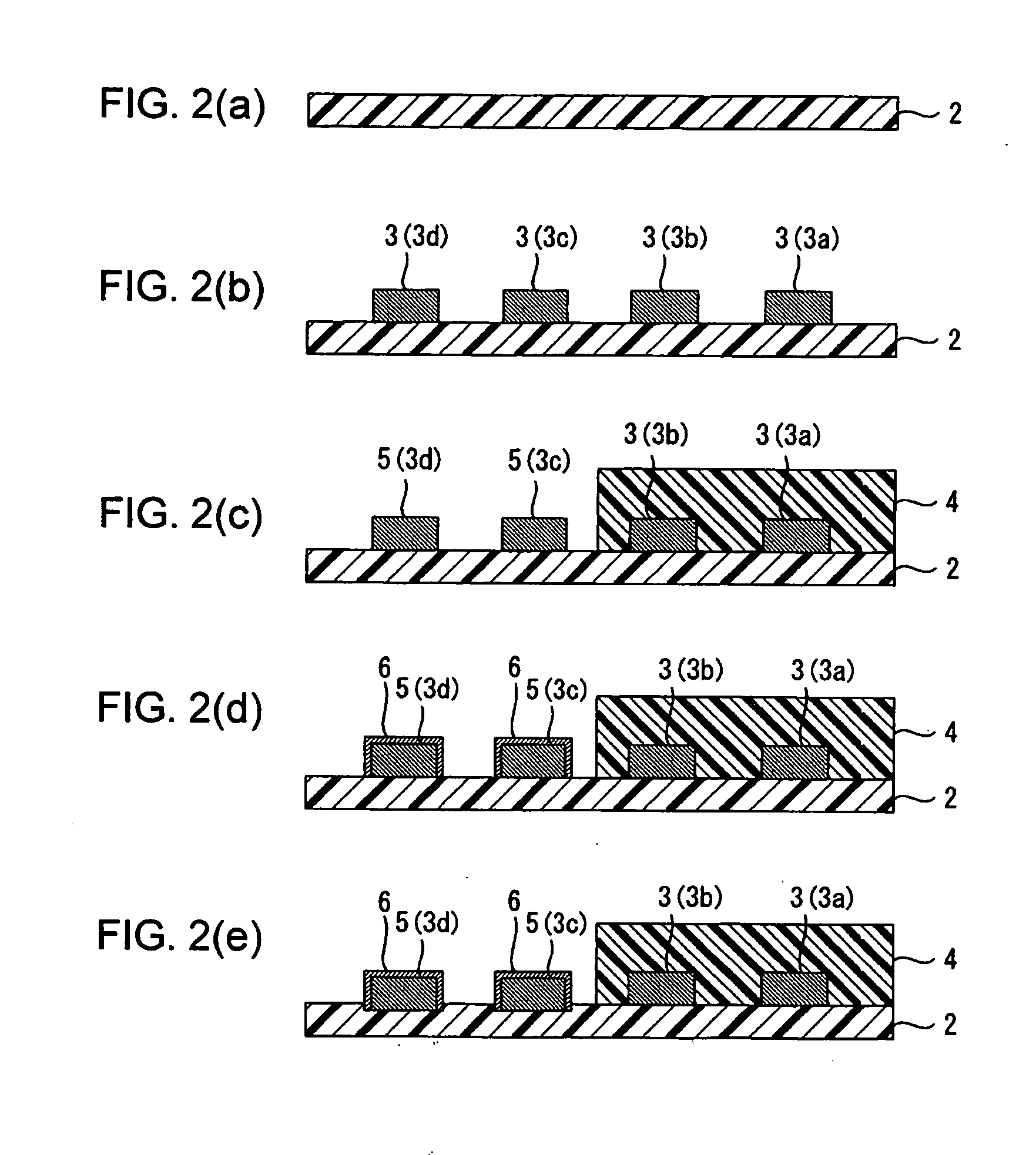
[0070] An insulating base layer formed by a polyimide resin film having a thickness of 25 μm and a glass transition temperature of 230° C. was prepared, first (Cf. FIG. 2(a)).

[0071] Then, a thin metal film was formed on the insulating base layer by sputtering a thin chromium film having a thickness of 0.03 μm and a thin copper film having a thickness of 0.10 μm sequentially. Then, a plating resist of a reverse pattern to the conductive pattern was formed on the thin metal film. Thereafter, a conductive pattern formed from copper was formed by electrolytic copper plating on a surface of the insulating base layer exposed from the plating resist. Thereafter, the plating resist was stripped and then the thin metal film exposed from the conductive pattern was removed by wet etching. As a result, the conductive pattern having a thickness of 10 μm was formed in a pattern comprising a plurality of wires which were spaced from each other at a distance of 30 μm (Cf. FIG. 2(b)).

[0072] Then, ...

example 2

[0075] An insulating base layer formed by laminating an insulating over layer formed by a polyimide resin film having a thickness of 5 μm and a glass transition temperature of 230° C. on an insulating under layer formed by a polyimide resin film having a thickness of 20 μm and a glass transition temperature of 350° C. was prepared (Cf. FIG. 3(b)).

[0076] Then, a conductive pattern having a thickness of 10 μm was formed in a pattern comprising a plurality of wires spaced from each other at a distance of 30 μm in the same manner as in Example 1 (Cf. FIG. 3(c)).

[0077] Further, an insulating cover layer, formed by a polyimide resin having a thickness of 15 μm, for covering the conductive pattern was formed on the insulating base layer in the same manner as in Example 1 (Cf. FIG. 3(d)).

[0078] Then, a gold plating layer having a thickness of 0.5 μm was formed on surfaces of each terminal portion in the same manner as in Example 1 (Cf. FIG. 3(e)). Thereafter, the terminal portions were s...


PUM

PropertyMeasurementUnit
Tgaaaaaaaaaa
thicknessaaaaaaaaaa
thicknessaaaaaaaaaa

Abstract

A wired circuit board which even when a conductive pattern is formed in the form of fine pitch can provide improved adhesion between the conductive pattern and an insulating layer to prevent a plating solution from remaining between a metal plating layer and the insulating layer, so as to prevent ionic impurities in the plating solution from remaining as residual or ionic contamination, whereby even when electric current flows through the circuit under a high temperature and high humidity environment over a long term, a short circuit from ionic migration can be prevented to suppress insulating failure. Lower end portions of terminal portions 5 formed on an insulating base layer 2 and lower end portions of side surfaces and metal plating layers 6 covering over the terminal portions 5 are embedded in the insulating base layer 2 in a flexible wired circuit board 1 at one longitudinal end portion thereof exposed from an insulating cover layer 4. This can provide the result of preventing infiltration of the plating solution in between the metal plating layers 6 and the insulating base layer 2 when the metal plating layer 6 is formed.

Description

BACKGROUND OF THE INVENTION [0001] 1. Field of the Invention [0002] The present invention relates to a wired circuit board and, more particularly, to a wired circuit board used for electronics. [0003] 2. Description of the Prior Art [0004] In general, a wired circuit board, such as a flexible wired circuit board, comprises an insulating base layer, a conductive pattern formed on the insulating base layer, and an insulating cover layer formed on the insulating base layer to cover the conductive pattern. [0005] This general wired circuit board is required to improve adhesion of the conductive pattern to the insulating base layer to prevent stripping of the conductive pattern from the insulating base layer, for improvement in fine pitch of the conductive pattern. [0006] For example, a technique has been proposed to ensure the adhesion of the circuit to the insulating layer by adhesively bonding a resin film consisting primarily of thermosetting resin to a substrate to form an insulatin...

Claims


Application Information

Patent Timeline
Patent Type & Authority Applications(United States)
IPC IPC(8): H05K1/00
CPCH05K1/117H05K3/107H05K3/22H05K3/244H05K2201/0769Y10T29/49156Y10T29/4913Y10T29/49153Y10T29/49155Y10T29/49126Y10T29/49165H05K2203/0278
Inventor ODA, TAKASHIMIYAKE, YASUFUMIOHKAWA, TADAO
Owner NITTO DENKO CORP
Why Eureka
Try Eureka