DC power source apparatus

a power source apparatus and transformer technology, applied in the direction of electric variable regulation, process and machine control, instruments, etc., can solve the problems of increasing the leakage inductance between the primary and secondary windings, and achieve the effect of reducing parasitic capacitance, increasing the distance between the primary and secondary windings, and simplifying the transformer 1b structur

Active Publication Date: 2006-03-02
SANKEN ELECTRIC CO LTD
View PDF2 Cites 7 Cited by
  • Summary
  • Abstract
  • Description
  • Claims
  • Application Information

AI Technical Summary

Benefits of technology

[0018] The shield plate 17 of FIG. 5 used to reduce the parasitic capacitance of the first and second primary windings complicates the structure of the transformer 1b and increases the distance between the primary and secondary windings by the thickness of the shield plate 17. This results in increasing leakage inductance between the primary and secondary windings. Accordingly, the related art of FIG. 5 is inappropriate to form a partial voltage resonance converter that uses a flyback voltage produced on a secondary winding to realize a zero-cross switch (zero-voltage switch ZVS).

Problems solved by technology

This results in increasing leakage inductance between the primary and secondary windings.

Method used


Image

  • DC power source apparatus
  • DC power source apparatus
  • DC power source apparatus

Examples


Embodiment Construction

[0037] A DC power source apparatus according to an embodiment of the present invention will be explained in detail with reference to the accompanying drawings.

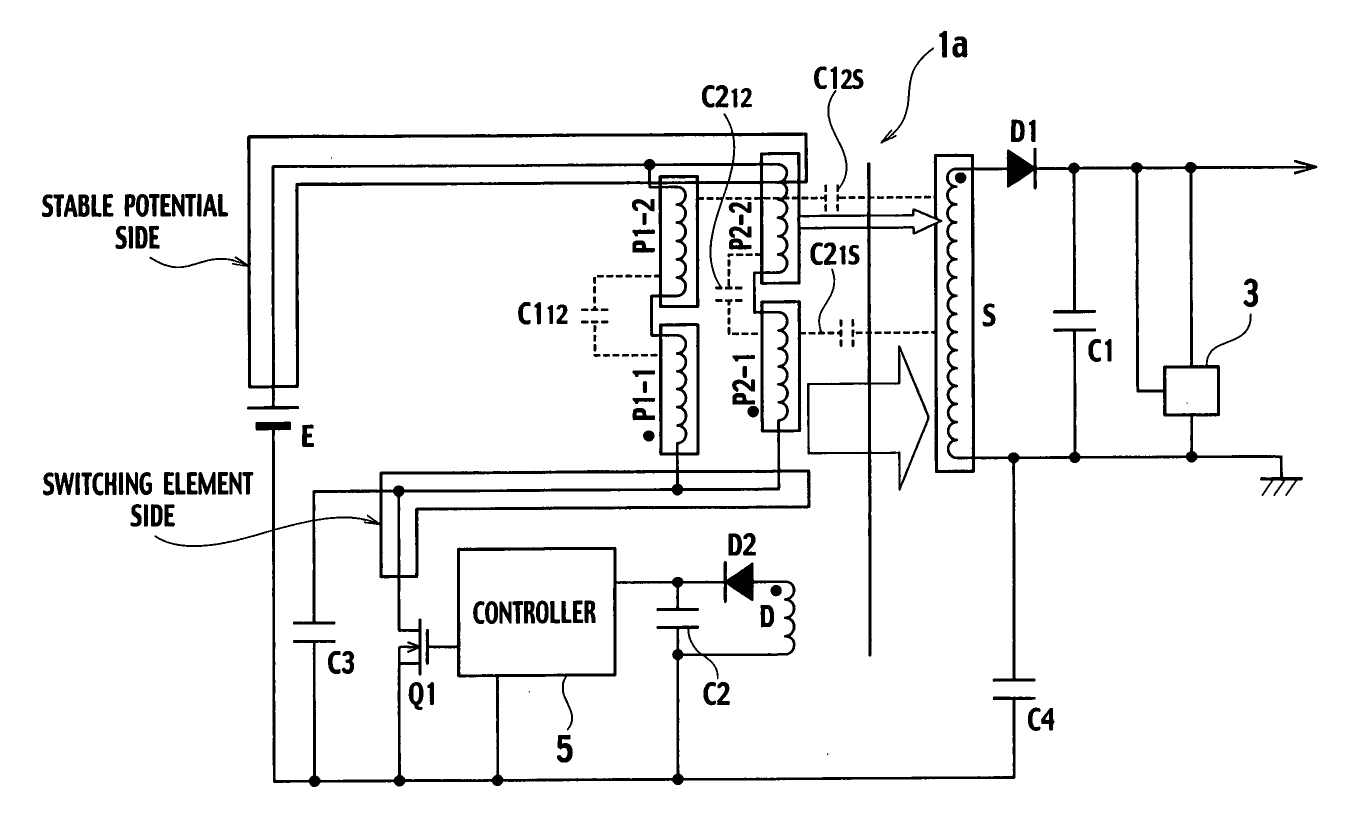
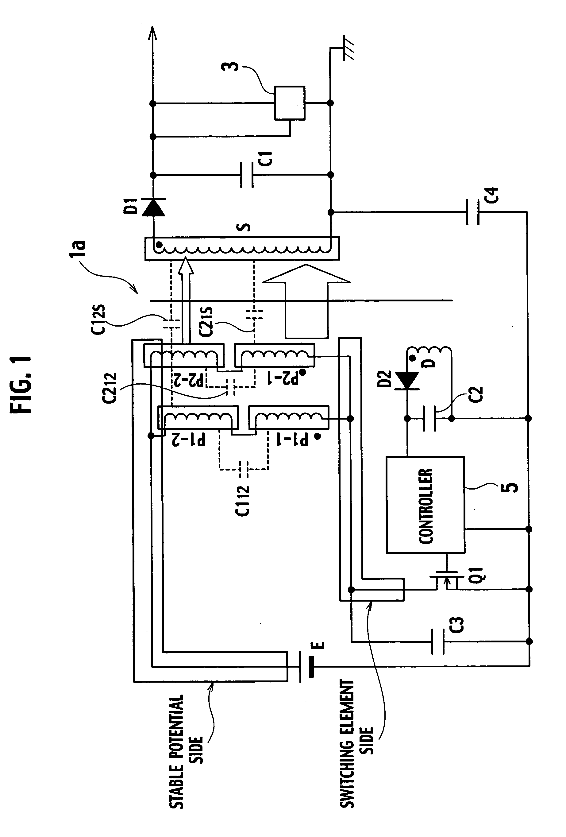
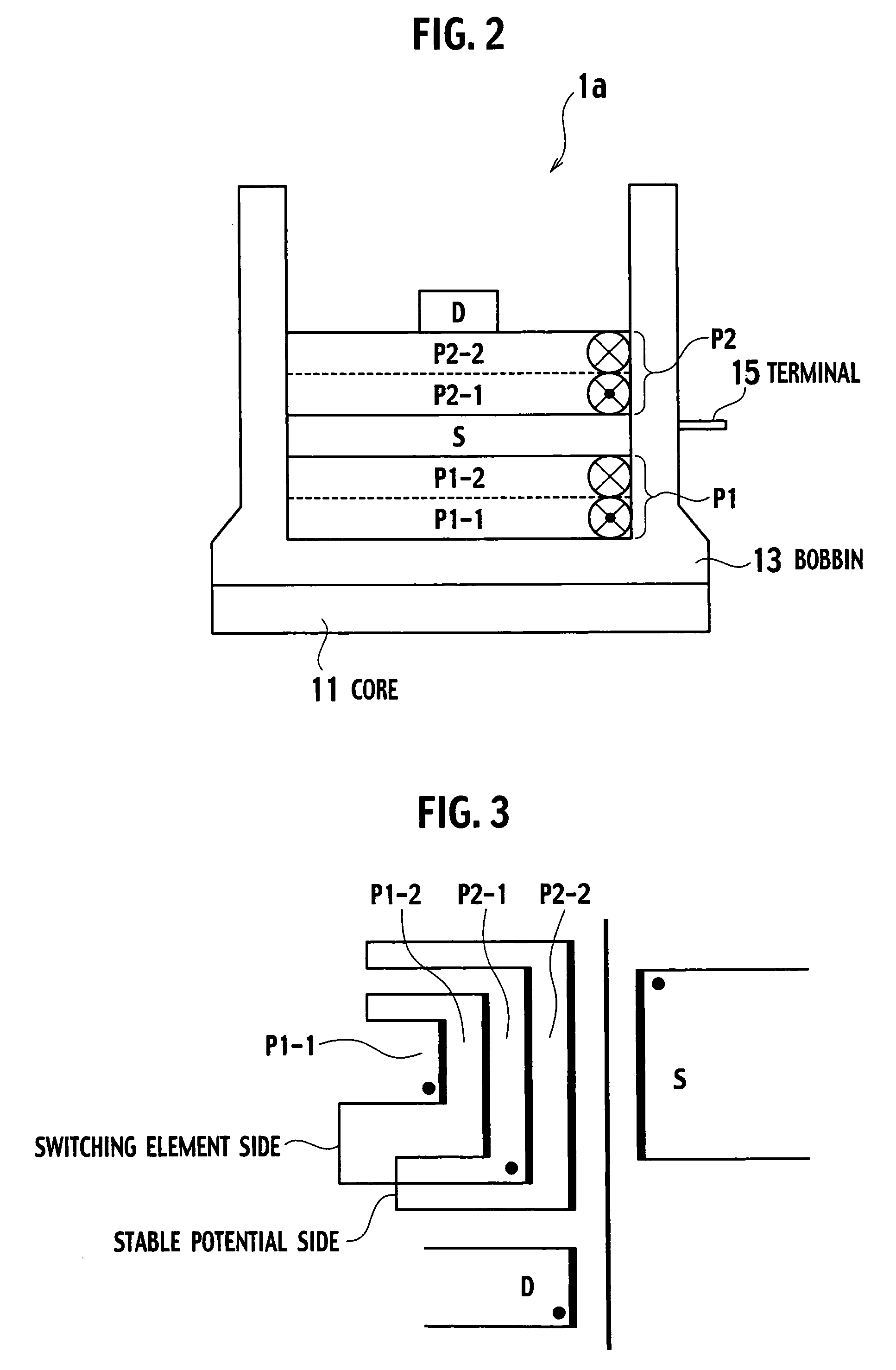
[0038]FIG. 8 is a sectional view showing a transformer arranged in the DC power source apparatus according to the embodiment. FIG. 9 is a view showing windings of the transformer of FIG. 8. FIG. 10 is a sectional view showing parasitic capacitance among the windings of the transformer of FIG. 8. FIG. 11 is a circuit diagram showing the DC power source apparatus employing the transformer of FIG. 8.

[0039] In FIG. 8, the transformer 1 has a core 11 made of magnetic material. The core 11 is inserted into a bobbin 13. Inside the bobbin 13, a first primary winding P1, a secondary winding S, a second primary winding P2a, and a tertiary winding D are sequentially arranged. The first primary winding P1 has winding layers P1-1 and P1-2. The second primary winding P2a has winding layers P2-2 and P2-1.

[0040] Forming of the windings in ...


PUM


Abstract

A DC power source apparatus has a DC power source for supplying a DC voltage, a transformer, and a switching element connected to a primary winding of the transformer. The switching element carries out ON/OFF operations to convert the DC voltage from the DC power source into high-frequency power, which is transferred to a secondary winding of the transformer and is converted into a DC output voltage. The primary winding of the transformer consists of a first primary winding made of a plurality of winding layers and a second primary winding made of a plurality of winding layers. The first and second primary windings are connected in parallel. The first primary winding is arranged on an inner side of the secondary winding, and the second primary winding is arranged on an outer side of the secondary winding. A terminal of a winding layer farthest from the secondary winding among the winding layers of each of the first and second primary windings is connected to the switching element.

Description

BACKGROUND OF THE INVENTION [0001] 1. Field of the Invention [0002] The present invention relates to a DC power source apparatus, and particularly, to a power converting transformer for a DC power source apparatus. [0003] 2. Description of the Related Art [0004]FIG. 1 is a circuit diagram showing a DC power source apparatus according to a related art. In the apparatus of FIG. 1, a DC power source E supplies a DC voltage. A switching element Q1 is, for example, a MOSFET and carries out ON / OFF operations to convert the DC voltage from the DC power source E into high-frequency power. A transformer 1a is connected between the switching element Q1 and a positive electrode of the DC power source E, so that the high-frequency power is transmitted from the primary side of the transformer 1a to the secondary side thereof. The high-frequency power on the secondary side of the transformer 1a is converted into a DC output voltage through a rectifying / smoothing circuit consisting of a diode D1 a...

Claims


Application Information

Patent Timeline
Patent Type & Authority Applications(United States)
IPC IPC(8): H02M3/335
CPCH01F27/2823H01F27/36H01F27/38H02M2001/123H01F2038/026H02M3/33523H01F41/0633H01F41/082H02M1/123H01F27/363
Inventor UTSUNO, MIZUKITAKAHASHI, YOSHIKAZUCHIKASHIGE, HIROYUKIKOIWAI, HIROMI
Owner SANKEN ELECTRIC CO LTD
Why Eureka
Try Eureka