Active type harmonic suppression apparatus

a harmonic suppression and active technology, applied in the direction of reducing harmonics/ripples, dc circuits to reduce harmonics/ripples, active power filtering, etc., can solve the problem that the electric power equipment may generate a large amount of harmonic current, transformer overheat, rotary machine vibration,

Active Publication Date: 2006-03-02
ABLEREX ELECTRONICS CO LTD
View PDF9 Cites 42 Cited by
  • Summary
  • Abstract
  • Description
  • Claims
  • Application Information

AI Technical Summary

Benefits of technology

[0011] In the control circuit, a load current, a utility current, an output current of the power converter, a power source voltage and a dc voltage of the power converter are detected and calculated to generate an expected output voltage. The expected output voltage is sent to a pulse width modulation circuit to generate a switching signal for

Problems solved by technology

These electric power equipment may generate a large amount of harmonic currents due to the nonlinear input characteristic of such loads.
The harmonic currents may result in the problems, such as transformer overheat, rotary machine vibration, voltage quality degradation, electric power components damage, medical facilities malfunction etc.
In general, the passive power filter may cause the resonance problem that may generate larger harmonic current and voltage.
The resonance of the passive power filter may damage the passive power filter itself and neighboring power facilities.
Additionally, it is quite hard to obtain a better filtering effect of the passive power filter due to the system reactance that may easily affect the filtering characteristic of the passive power filter.
Furthermore, the harmonic current of neighboring non-linear loads may flow into the passive power filter and result in overload of the passive power filter.
Therefore, the manufacture cost of the power converter of the active power filter must be significantly increased so that applications of the active power filter are disadvantageously limited.
However, a

Method used


Image

  • Active type harmonic suppression apparatus
  • Active type harmonic suppression apparatus
  • Active type harmonic suppression apparatus

Examples


Embodiment Construction

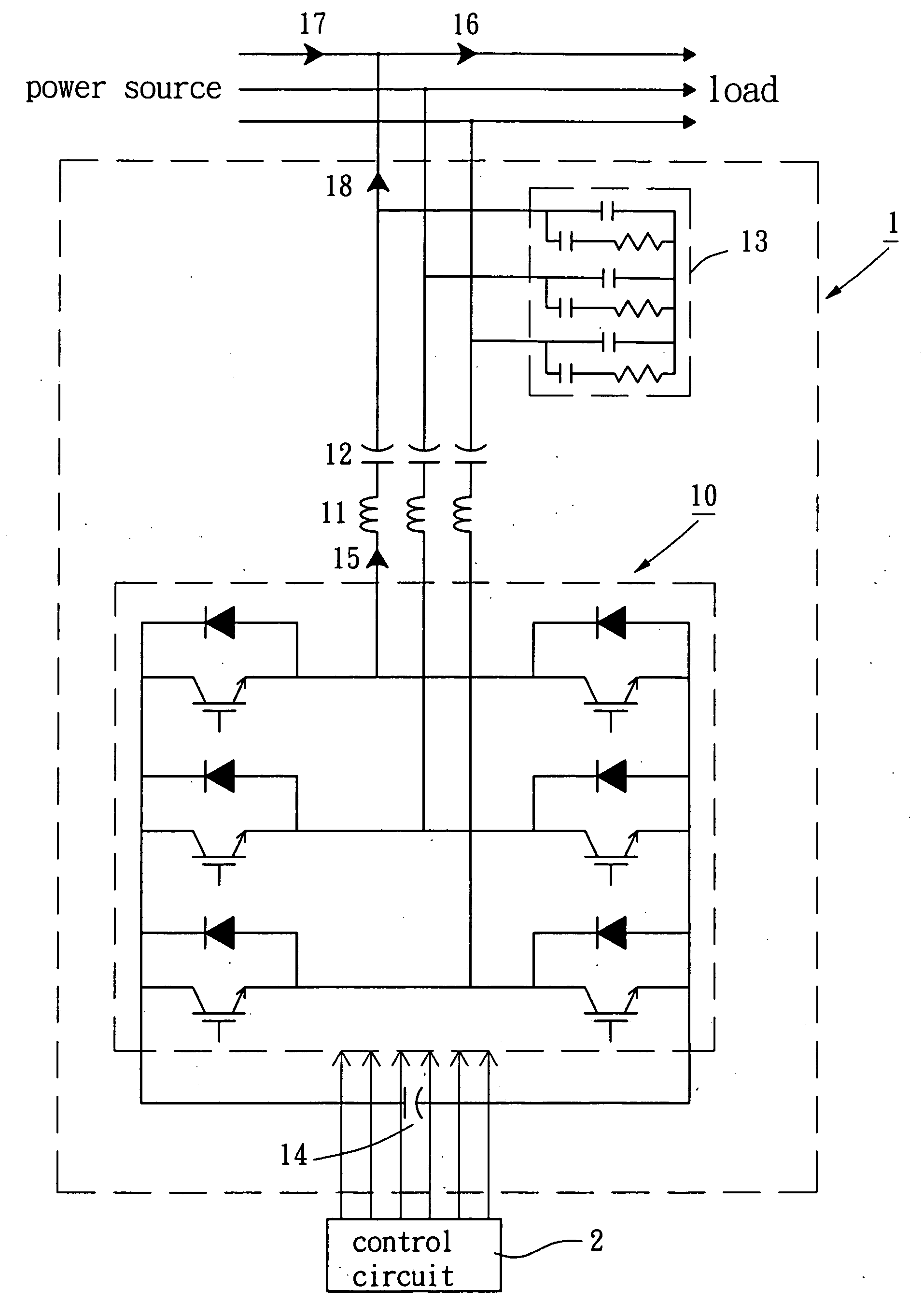
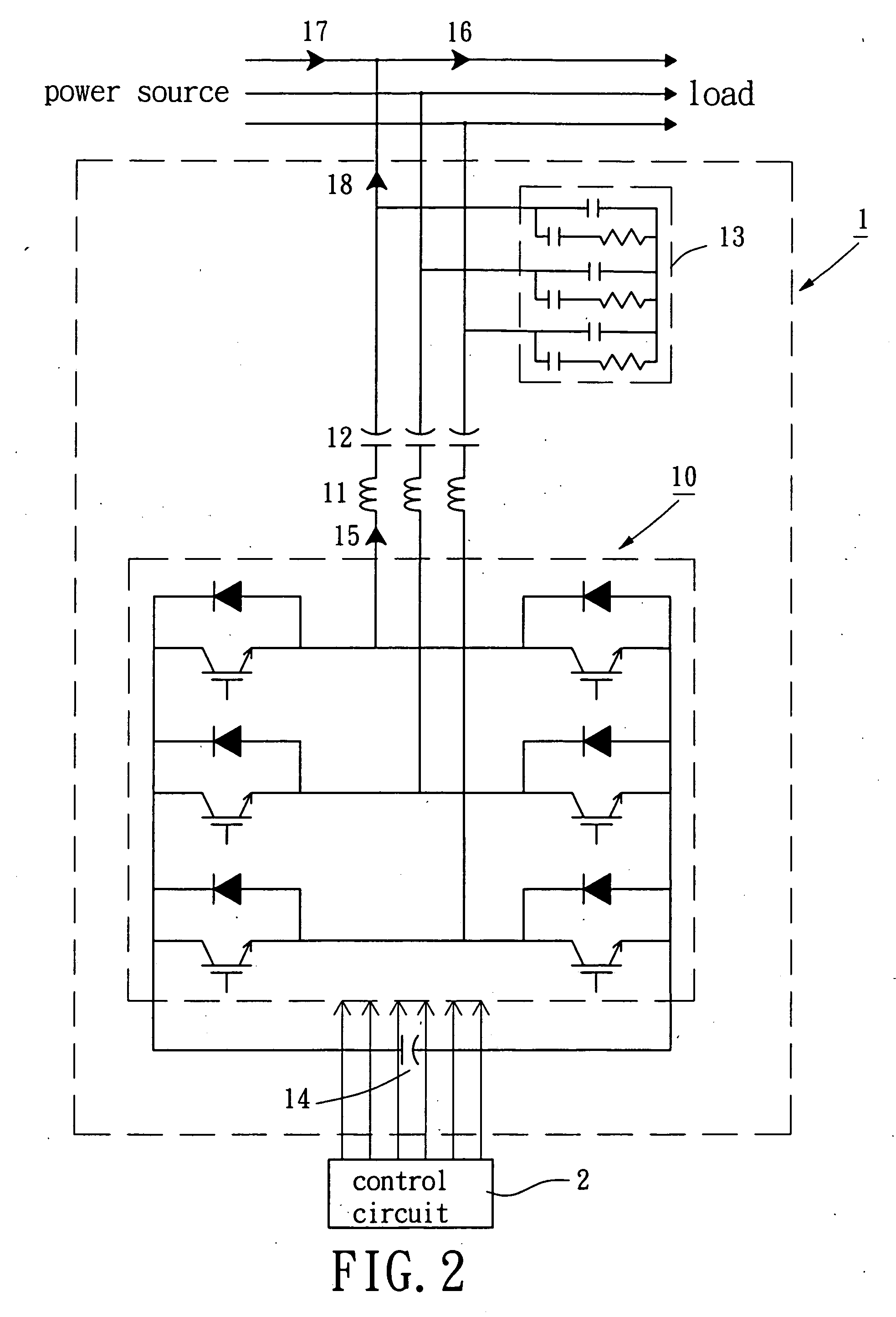
[0020] Referring to FIG. 2, a schematic circuitry of an active type harmonic suppression apparatus in accordance with the present invention is illustrated. The active type harmonic suppression apparatus 1 includes a power converter 10, a filter inductor 11, a reactive power compensating capacitor set 12, a combined capacitor / resistor filtering set 13, a dc power capacitor 14 and a control circuit 2. The dc power capacitor 14 acts as a power storage element for supplying a first dc voltage. The power converter 10 includes a power electronic device set and electrically connects with the dc power capacitor 14 so as to convert the first dc voltage into a compensation voltage. The filter inductor 11, the reactive power compensation capacitor 12 and the combined capacitor / resistor filtering set 13 converts the compensation voltage into a compensation current 18 for injecting into a power feeder that may filter harmonic components of a load current 16. Consequently, a utility current 17 ca...


PUM


Abstract

An active type harmonic suppression apparatus, connected in parallel to a power feeder, supplies a compensation current for injecting into the power feeder such that a utility current of a power source is approached to a sinusoidal wave. The control circuit retrieves a load current, a utility current, an output current of the power converter, a power source voltage and a voltage of the dc power capacitor for calculating and sending a reference signal of compensation voltage to a pulse-width-modulation circuit which generates switching signals for the power converter. Furthermore, the harmonic suppression apparatus can provide a fixed or variable reactive power.

Description

BACKGROUND OF THE INVENTION [0001] 1. Field of the Invention [0002] The present invention relates to an active type harmonic suppression apparatus. More particularly, the present invention relates to the active type harmonic suppression apparatus connected in parallel to a power feeder for filtering harmonic currents thereof. [0003] 2. Description of the Related Art [0004] Recently, the controllable power electronic devices suitable for high voltage rating and large current rating characteristics have been developed due to the improvement of the semiconductor manufacturing technique. Power electronic devices are widely applied in electric power equipment, such as motor driver, arc furnace, trolley car, battery charger, and lighting appliance etc. These electric power equipment may generate a large amount of harmonic currents due to the nonlinear input characteristic of such loads. The harmonic currents may result in the problems, such as transformer overheat, rotary machine vibratio...

Claims


Application Information

Patent Timeline
IPC IPC(8): H02M1/12H02J3/01H02J3/18
CPCH02J3/01Y02E40/40Y02E40/22H02J3/1842Y02E40/20
Inventor WU, CHIN-CHANGCHOU, HUNG-LIANGFENG, YA-TSUNGHSU, WEN-PINCHANG, YAO-JEN
Owner ABLEREX ELECTRONICS CO LTD
Why Eureka
Try Eureka