
Thermoelectric devices with controlled current flow and related methods

a technology of current flow and thermoelectric device, applied in the direction of thermoelectric device, electric apparatus, nanotechnology, etc., can solve the problem of relatively low operation efficiency of devices, achieve the effect of improving cooling performance, increasing thermal separation and isolation, and improving thermoelectric performan

Inactive Publication Date: 2006-03-09
OROBRIDGE
View PDF32 Cites 89 Cited by
  • Summary
  • Abstract
  • Description
  • Claims
  • Application Information

AI Technical Summary

Benefits of technology

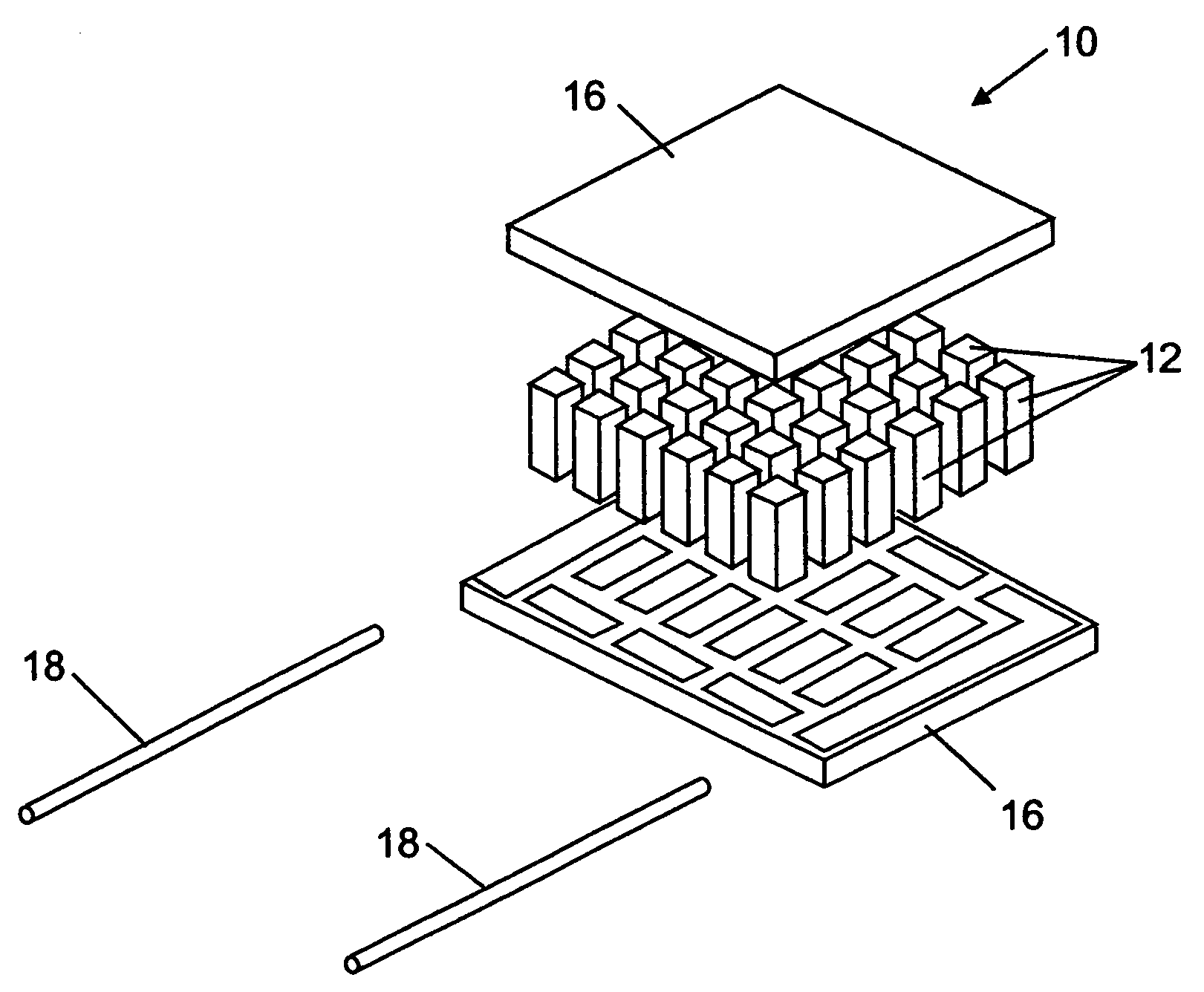
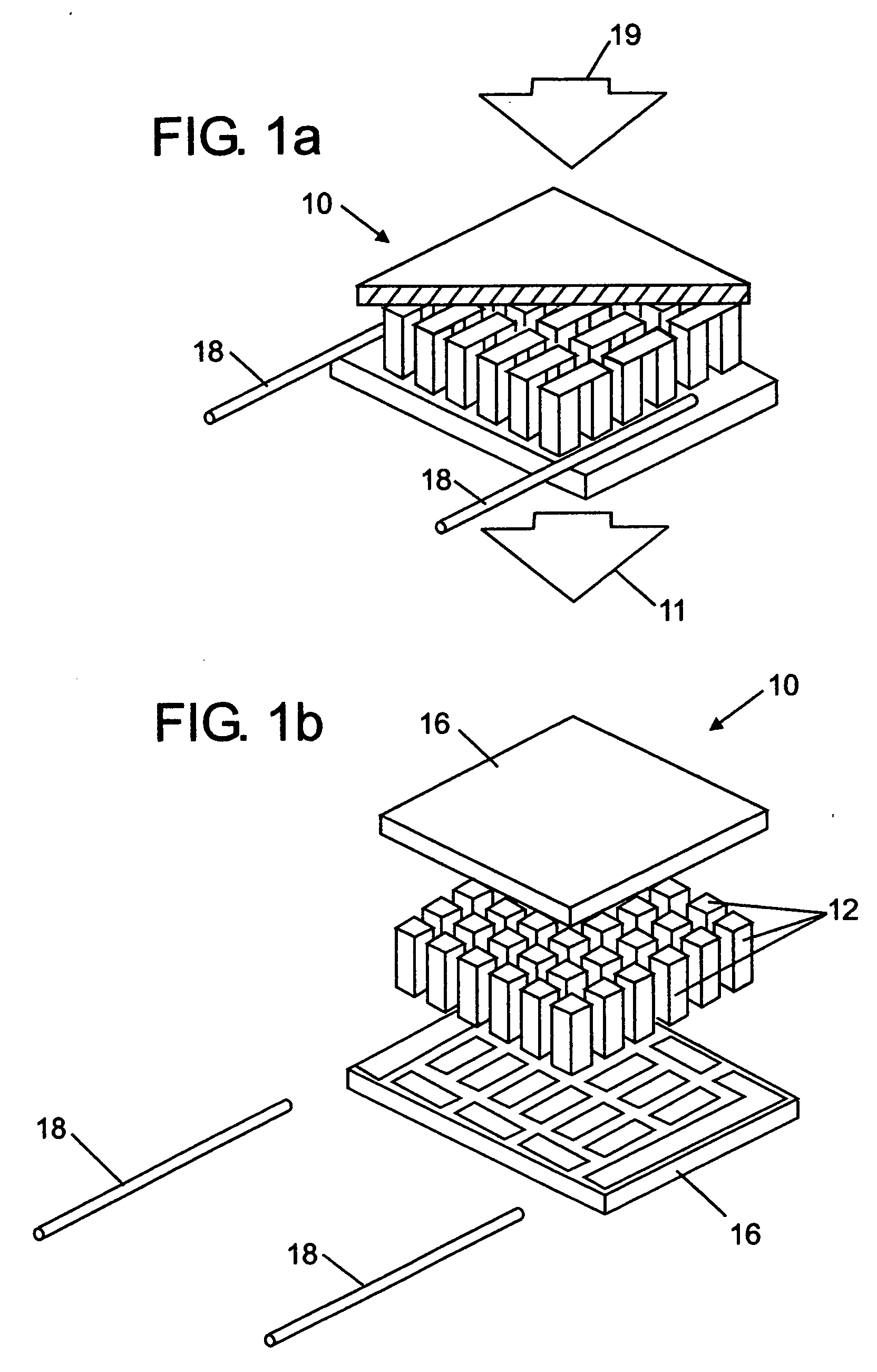
[0011] A number of embodiments of the present invention provide thermoelectric devices with controlled and / or guided electric current flow that can increase the effective Peltier cooling by reducing the associated Joule heating. In some embodiments of the present invention, thermoelectric devices are provided in which the effective electrical resistance of the semiconductive material disposed between the hot and cold junctions is reduced below the effective electrical resistance of semiconductive material. Differences in the effective resistances seen along the electrical current path between the hot and cold junctions may also be used to control or direct the current as desired through some thermoelectric device embodiments. In addition, designing the effective electrical and thermal resistances can help reduce Joule heating between the junctions. Further, designing the effective electrical and thermal resistances can be used to better manage the Peltier effect and help improve thermal isolation across a thermoelectric device. Some embodiments can combine electrical current from different sources or divide electric current flow at various points between the hot and cold junctions of a thermoelectric device, seeking to improve thermoelectric device performance. Other embodiments use a variety of types of materials, a variety of physical structures, a variety of thermal configurations, and a variety of electrical configurations in thermoelectric devices. Insulators, conductive segments, and semiconductive segments of thermoelectric devices can be designed to improve the overall thermoelectric operation of thermoelectric devices.
[0012] Several embodiments of the present invention provide thermoelectric devices that thermally isolate the hot and cold junctions. For example, this is possible by increasing the distance between the two junctions while reducing the Joule heating therein, by designing the desired thermal conductivity, by designing the desired electrical resistance, and the like. Thermally isolating the hot and cold junctions helps to counteract heat leakage that interferes with Peltier heat transfers between the junctions. Thermoelectric devices according to some embodiments provide intervening structures that allow Peltier heating and Peltier cooling to counteract each other between the hot and cold junctions. Other embodiments include thermoelectric devices containing a variety of intervening structures between the hot and cold junctions that can better support thermoelectric operation therein. While some thermoelectric device embodiments operate as Peltier coolers when electrically powered in one polarity, those embodiments are also operable as Peltier heaters reversibly when electrically powered in the opposite polarity. These thermoelectric device embodiments can also use the Seebeck effect to generate electrical power from ambient thermal energy.
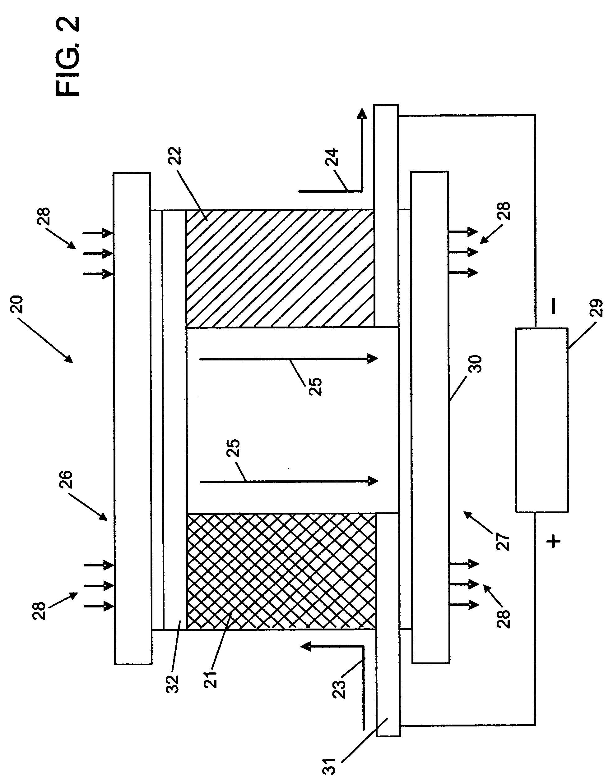
[0014] For the above and other embodiments, the effective electrical resistance between the first conductive material and the third conductive materials can be controllably reduced below the effective series electrical resistances of the first semiconductive material and the second semiconductive material by design as electrical current flows through the conductive materials. Reducing the effective electrical resistance between the first conductive material and the third conductive material can produce correspondingly lower Joule heating therebetween. Thus, the associated Joule heating may be reduced between the first conductive material and the third conductive material as electrical current flows therebetween. In addition, the Peltier cooling and Peltier heating can counteract each other within the second conductive material or the like as electrical current flows therethrough. Thus, the effective Peltier cooling may be increased while Joule heating may be reduced when the thermoelectric device is operated in cooling mode. This is also the case when thermoelectric embodiments are operated as Peltier thermoelectric heaters or Seebeck thermoelectric power generators. Thus, heat can be exchanged between the first conductive material and the third conductive material creating a temperature differential between the first conductive material and the third conductive material as electrical current flows therebetween.
[0017] A number of embodiments use nanotubes, nanowires, nanomaterials, superlattice materials, or other materials for the semiconductive material, conductive material, or for both. The semiconductive and conductive materials can be arranged in various configurations with respect to the direction of electrical current flow, such as in series, in parallel, or in combinations thereof in embodiments. The semiconductive and conductive materials can also be arranged in various configurations, angles, and configurations with respect to the direction of thermal energy flow between the hot and cold junctions. Further, the semiconductive and conductive materials can also be arranged in various configurations, angles, and configurations with respect to the direction of electrical current flow. Interleaved semiconductive material areas adjoining conductive material areas between the hot and cold junctions can help improve thermoelectric performance. These interleaved material areas serve to improve the cooling performance by creating more thermal separation and isolation between the hot and cold junctions. These interleaved areas or material segments can also be configured seeking to separate the electrical current flow path from the thermal energy flow path. Further, the interleaved material areas can allow localized Peltier cooling and Peltier heating to counteract within the interleaved areas between the hot and cold thermal junctions. Also, the intervening material areas may help reduce the associated Joule heating as electrical current flows through the device. Embodiments are provided in which the electrical current path between the hot and cold junctions is separated from the thermal conduction path between the hot and cold junctions through the intervening conductive and semiconductive areas. For example, one way this may be accomplished by providing different effective lengths for the electrical current path and the thermal conduction path between the hot and cold junctions of a thermoelectric device. The electrical current path may be guided through a different path than the path through which heat is conducted by design. A set of embodiments provides a current path shorter than the thermal path, while other embodiments provide a current path longer than the thermal path. In addition, differences in thermal conductivity, electrical resistance, both, or the like in the intervening areas can be used to improve thermoelectric operation by design.
[0018] Additional embodiments of thermoelectric devices are provided including means for separating the electrical current path creating Peltier heat exchanges that provide Peltier heating or cooling from the thermal path conducting transferred heat between the hot and cold junctions. Some embodiments include means for conducting electricity and means for semiconducting electricity. Embodiments including means for increasing the distance between the hot and cold junctions while reducing the associated Joule heating occurring between the hot and cold junctions as electrical current flows therebetween are also provided. Further embodiments include means for controllably reducing the effective electrical resistance below that of means for semiconducting electricity disposed between the hot and cold junctions. In addition, some embodiments provide means for controllably counteracting Peltier heating by Peltier cooling between the junctions. Some embodiments of thermoelectric devices provide means for isolating the hot and cold junctions created by Peltier heat exchanges that provide heating or cooling when electrical current flows through the thermoelectric device or through the means for reducing the effective electrical resistance.

Problems solved by technology

However, these devices still have relatively low efficiencies in operation.

Method used


Image

  • Thermoelectric devices with controlled current flow and related methods
  • Thermoelectric devices with controlled current flow and related methods
  • Thermoelectric devices with controlled current flow and related methods

Examples


embodiment 170

[0077] Based on these principles, an example structure of thermal legs with current guidance and current control in a thermal leg is illustrated in FIG. 8. This figure shows a thermoelectric device embodiment 170 containing various interconnected thermal legs, such p-type thermal leg 171 and n-type thermal leg 172. Current 174 is directed through the device as shown by the arrows. Note that electrical current tends to flow more down the path containing less electrical resistance—thus resistances in the current path can be designed so as to direct the current in the desired direction. For example, the resistance of conductive material such as 173 is generally lower than the resistance of p-type semiconductive material such as 175 or the resistance of n-type semiconductive material such as 176. Electrical current 174 entering the hot junction 177 at the bottom is forced to pass through p-type semiconductive material 175 on its path to the cold junction 178 because the semiconductive m...

embodiment 240

[0127] It is also possible to create improved thermal leg embodiments and thermoelectric device embodiments by leveraging nanotechnology developments. FIGS. 17(a) and 17(b) are diagrams illustrating possible differences in the separation possible within thermoelectric legs according to some thermoelectric device embodiments of the present invention. FIG. 17(a) shows a thermoelectric leg embodiment 240 similar to some previously described. Thermal leg 240 contains various conductive material segments such as 243. In addition, the thermal leg contains various semiconductive material segments such as 244. The electric current flows through the semiconductive segments as shown by arrows 242. The possible separation 247 is determined by trading off the increase in thermal isolation against the increased electrical resistance. Ideally, it helps thermoelectric operation to increase the separation and resulting thermal isolation between the hot and cold junctions of the device. One way to a...

embodiment 260

[0130] FIGS. 19(a), 19(b), 19(c), and 19(d) illustrate some thermoelectric device structure embodiments and thermoelectric thermal leg embodiments according to the present invention. First, FIG. 19(a) illustrates a thermoelectric leg embodiment 260 which has guided and controlled electrical current flow through the leg. Conductive material segments, such as 266, 266(a), 266(b), and similarly designated conductive material areas are shown. Electrical currents, such as 264(a) and 264(b), enter the thermal leg in parallel from the left through conductive material segments in at least two points, such as through conductive material segments 266(a) and 266(b) respectively as shown. Insulators such as 261 and similarly designated insulating areas can be used to electrically isolate the different semiconductive material areas. In addition, the placement of the insulators as shown can cause each incoming current to divide, such as how current 264(a) is caused to split and enter p-type semic...


PUM


Abstract

Thermoelectric devices comprising at least a first conductive material, a first semiconductive material, a second conductive material, and a third conductive material. The second conductive material may be contacting, disposed within, or operably connected to the first semiconductive material. Semiconductive materials may be depleted, undoped, p-doped, or n-doped, nanotubes, nanowires, and others. Conductive materials may be metals, alloys, conductive materials, nanotubes, nanowires, and others. The effective electrical resistance between the first conductive material and the third conductive materials is reduced below the series electrical resistance of the first semiconductive material by design, reducing the associated Joule heating. Peltier cooling and Peltier heating counteract each other within the second conductive material as electrical current flows. Heat exchanged between the first conductive material and the third conductive material creates a temperature differential therebetween. Thermoelectric devices can reversibly heat or cool, and use the Seebeck effect to generate electrical power from thermal energy.

Description

CROSS REFERENCE TO RELATED APPLICATIONS [0001] This patent application claims the benefit of U.S. provisional application Ser. No. 60 / 608,329 filed Sep. 9, 2004, the entire contents of which are incorporated by reference herein. Further, this patent application claims the benefit of U.S. provisional application Ser. No. 60 / 622,776 filed Oct. 28, 2004, the entire contents of which are incorporated by reference herein.FIELD OF THE INVENTION [0002] The present invention generally relates to thermoelectric device technology based on the Peltier and Seebeck effects. More particularly, the present invention provides a class of thermoelectric devices with controlled electrical current flow that may be operated as thermoelectric coolers, thermoelectric heaters, or thermoelectric generators, and related methods. BACKGROUND OF THE INVENTION [0003] Thermoelectric devices that can convert between electrical energy and thermal energy have been in existence since the early 19th century. Seebeck, ...

Claims


Application Information

Patent Timeline
IPC IPC(8): H01L35/30H01L35/28
CPCB82Y10/00H01L35/32H01L35/04H10N10/81H10N10/17
Inventor ONVURAL, O. RAIF
Owner OROBRIDGE
Learn More