Magnetic recording medium, magnetic recording/reproducing apparatus, and stamper for manufacturing the magnetic recording medium

a technology of magnetic recording medium and recording medium, which is applied in the field of magnetic recording medium, magnetic recording/reproducing apparatus, and stamper for manufacturing the magnetic recording medium, can solve the problems of low productivity of the servo signal recording step, limited accuracy, and conventional approaches to the improvement of the density of the areal already reaching their limits, so as to achieve the effect of easy production and resistance to tracking errors

Inactive Publication Date: 2006-03-09
TDK CORPARATION
View PDF11 Cites 15 Cited by
  • Summary
  • Abstract
  • Description
  • Claims
  • Application Information

AI Technical Summary

Benefits of technology

[0018] In view of the foregoing problems, various exemplary embodiments of this invention provide a reliable magnetic recording medium which comprises a servo signal unit portions formed in a concavo-convex shape, easily produced, and resistant to tracking error. Various exemplary embodiments of this invention also provide a magnetic recording / reproducing apparatus which incorporates the magnetic recording medium. Various exemplary embodiments of this invention further provide a stamper for manufacturing the magnetic recording medium.

Problems solved by technology

However, such a servo signal recording step raised a problem of low productivity because in this step, the servo signal unit portions and their surrounding portions are magnetized in opposite polarities one by one in each magnetic recording medium.
However, these conventional approaches to the improvement of areal density have already reached their limits due to the limited accuracy in processing the magnetic head or recording to a track adjacent to a target track or crosstalk on reproducing operation caused by a spread of the recording magnetic field of the magnetic head.
However, it was not easy to form a desired servo pattern with accuracy in the resist layer.
For example, a concavo-convex shape corresponding to such a complicated servo pattern was not easy to form in the resist layer by lithography, and the concavo-convex shape was thus difficult to form with sufficient accuracy.
On the other hand, even in the case of using a stamper, since the stamper is also manufactured by lithography which has a transfer surface of a concavo-convex shape corresponding to that of the recording layer, there was a problem that the concavo-convex shape could not be formed on the stamper with sufficient accuracy.
Furthermore, even by dry etching, it was difficult to process the mask layer or the recording layer with accuracy exactly according to the shape of the patterned resist layer.
That is, it is not easy to accurately form a rectangular servo signal unit portions as a convex or concave portions exactly in the desired shape.
In particular, it is difficult to precisely form the rectangular servo signal unit portions exactly according to a complicated servo pattern, having an angular difference depending on the radial position, corresponding to the arcuate path of the magnetic head of the magnetic recording / reproducing apparatus.
As such, the servo signal unit portions disposed at an unintended angle may cause an unallowable angular difference between the servo signal unit portions and the magnetic head, leading to degradation in read accuracy of the servo information and thus resulting in an error.
More specifically, magnetic recording media, such as the discrete track medium and the patterned medium, which have high areal densities, are subject to tracking error due to degradation in accuracy in reading burst signals.

Method used


Image

  • Magnetic recording medium, magnetic recording/reproducing apparatus, and stamper for manufacturing the magnetic recording medium
  • Magnetic recording medium, magnetic recording/reproducing apparatus, and stamper for manufacturing the magnetic recording medium
  • Magnetic recording medium, magnetic recording/reproducing apparatus, and stamper for manufacturing the magnetic recording medium

Examples


working example

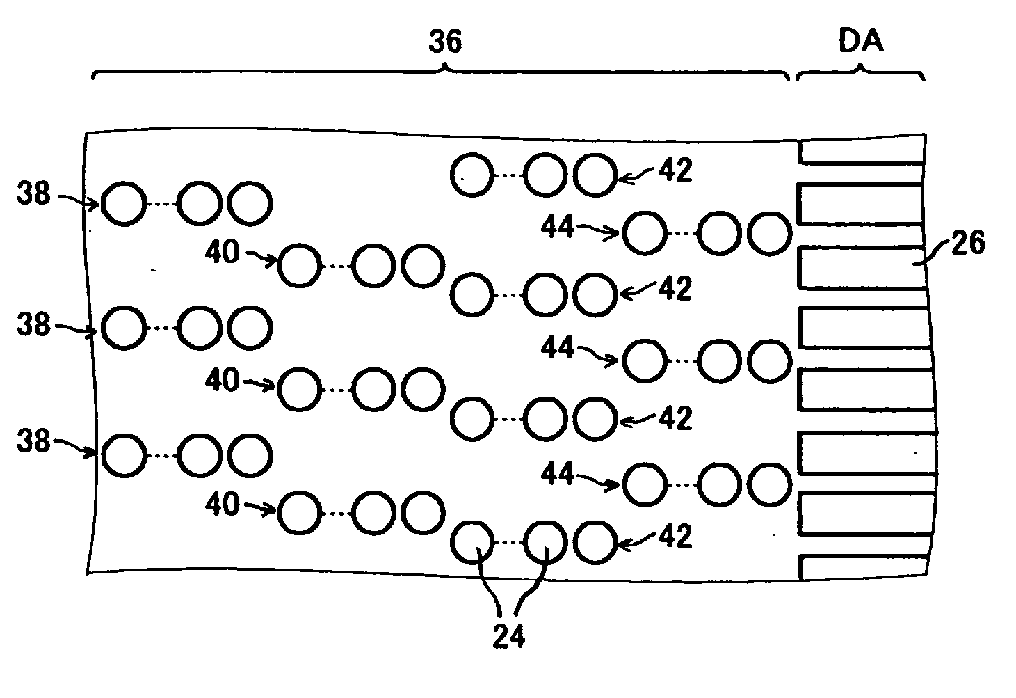
[0095] Twenty types of magnetic recording / reproducing apparatuses 10 were prepared which had the burst signal unit portions 24, generally elliptical in shape, formed in four types of separate burst signal groups, the apparatuses having different relations therebetween in the shape Rt / Rs of the burst signal unit portion 24 and the read width Wr of the magnetic head 14. The major configurations of these magnetic recording / reproducing apparatuses 10 are shown in Table 1.

[0096] In all the magnetic recording / reproducing apparatuses 10, the recording layer 21 of the magnetic recording medium 12 has a fixed thickness of approximately 15 nm, and the burst signal unit portions 24 also have a fixed radial width Rt of approximately 200 nm. A measurement of the magnetic property of the recording layer 21 performed using a vibrating sample magnetometer (VSM) showed that the saturation magnetization Ms was approximately 350 emu / cc and the remanent magnetization Mr was approximately 340 emu / cc.

[...


PUM

PropertyMeasurementUnit
thicknessaaaaaaaaaa
thicknessaaaaaaaaaa
thicknessaaaaaaaaaa

Abstract

A reliable magnetic recording medium is provided which comprises a servo signal unit portions formed in a concavo-convex shape, easily produced, and resistant to tracking error. Also provided are a magnetic recording/reproducing apparatus which incorporates the magnetic recording medium, and a stamper for manufacturing the magnetic recording medium with efficiency. The magnetic recording medium includes a recording layer divided into a plurality of data areas and a plurality of servo areas to record information. The recording layer is formed in a concavo-convex shape in each servo area, with a servo signal unit portions formed as either a convex portions or a concave portions of the concavo-convex shape. Of the servo signal unit portions, the burst signal unit portion for tracking is generally elliptical in shape when viewed from the direction of thickness.

Description

BACKGROUND OF THE INVENTION [0001] 1. Field of the Invention [0002] The present invention relates to a magnetic recording medium having servo signal unit portions formed in a concavo-convex shape, a magnetic recording / reproducing apparatus with the magnetic recording medium, and a stamper for manufacturing the magnetic recording medium. [0003] 2. Description of the Related Art [0004] Conventional magnetic recording media such as hard disks have been used with the recording layer divided into a plurality of data areas and a plurality of servo areas. In the servo area, control servo signals such as for positioning a magnetic head are magnetically recorded in a predetermined servo pattern. [0005] The servo area includes a preamble region for clock synchronization, a SAM region for indicating the start of servo data, a track address signal region for indicating the track number, a sector address signal region for indicting the sector number, and a burst signal region for tracking the ma...

Claims


Application Information

Patent Timeline
Patent Type & Authority Applications(United States)
IPC IPC(8): G11B5/86G11B5/09
CPCB82Y10/00G11B5/865G11B5/82G11B5/743
Inventor KAIZU, AKIMASAMORIYA, MAKOTOSOENO, YOSHIKAZU
Owner TDK CORPARATION
Why Eureka
Try Eureka