
Conductive endless belt and image forming apparatus using the same

Active Publication Date: 2006-03-09
ARCHEM INC
View PDF9 Cites 9 Cited by
  • Summary
  • Abstract
  • Description
  • Claims
  • Application Information

AI Technical Summary

Benefits of technology

[0024] Hence, an object of the present invention is to provide a conductive endless resin belt used in the tandem, intermediate transfer, and tandem type intermediate transfer image forming apparatuses and an image forming apparatus using the above conductive endless resin belt, the conductive endless resin belt having superior strength, in particular, superior folding endurance, stable and appropriate electrical resistance in high voltage application, less voltage dependence of electrical resistance, and superior durability in image output and transfer efficiency.
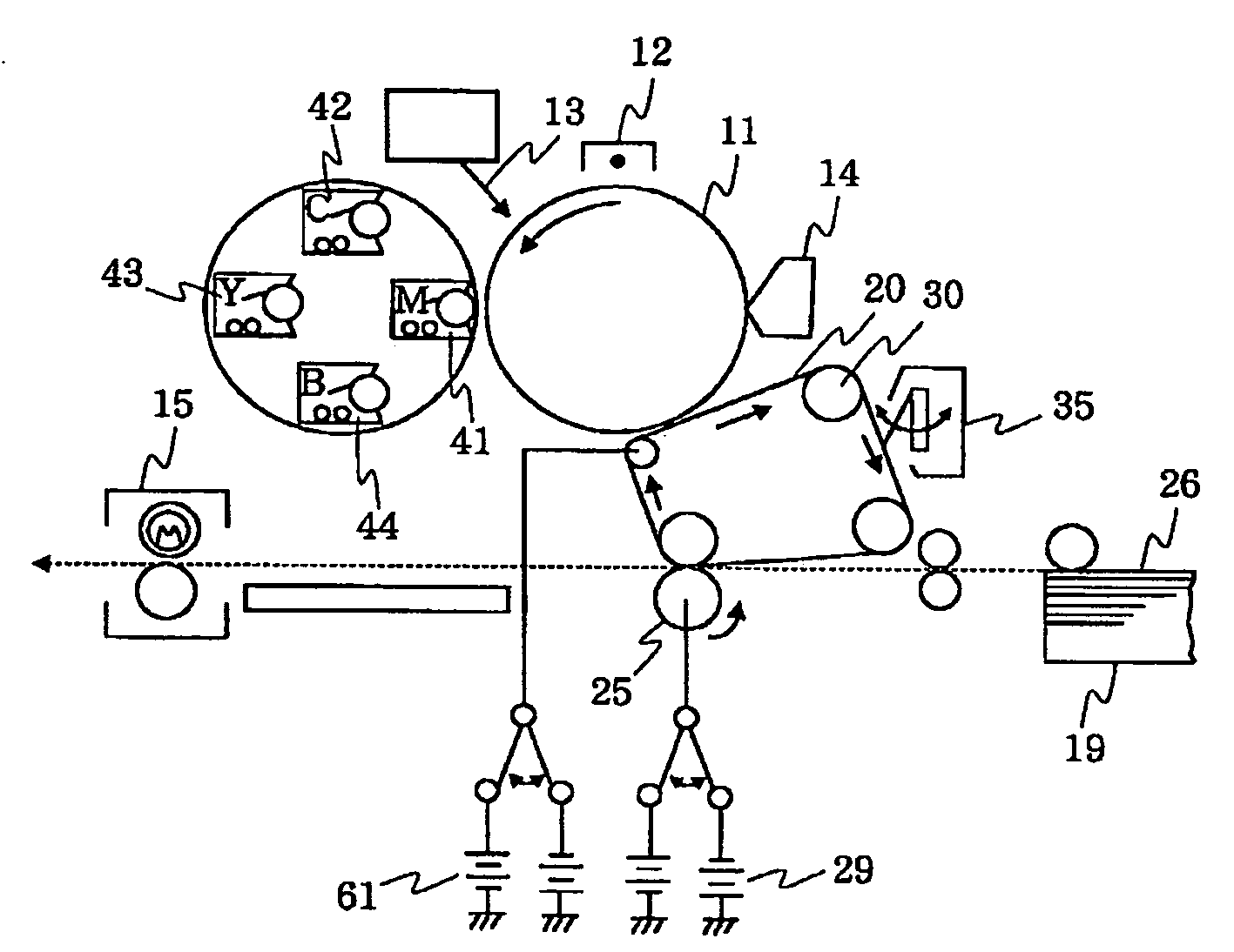
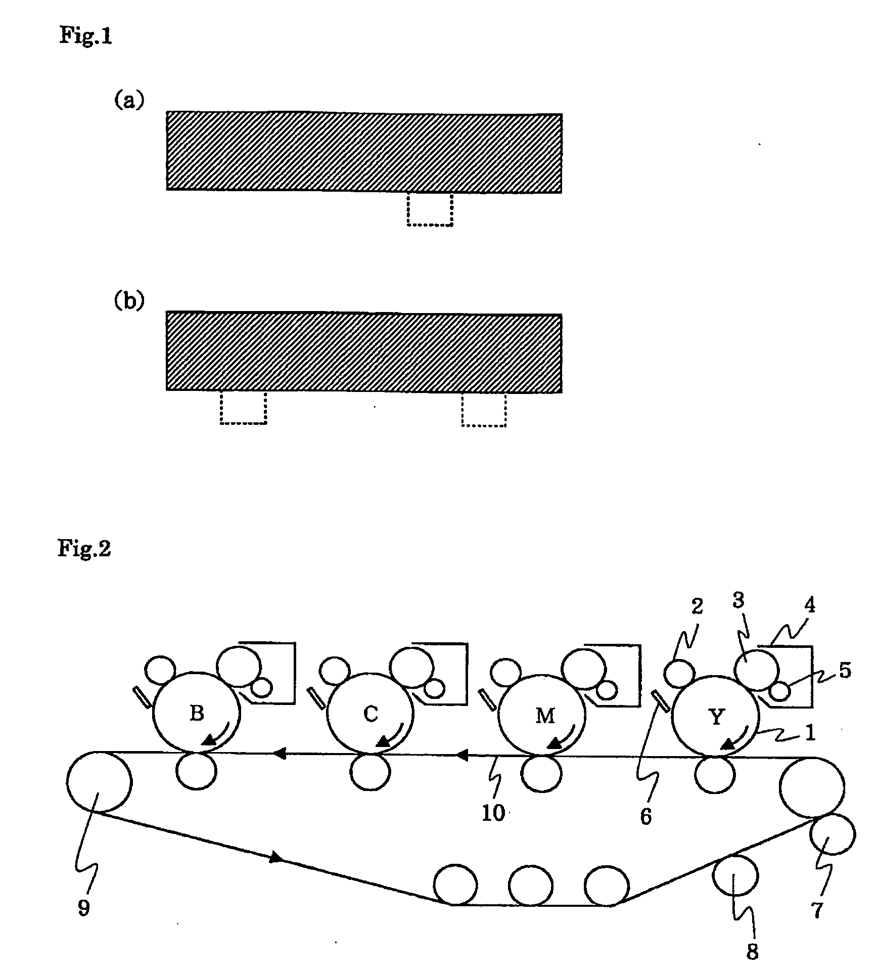
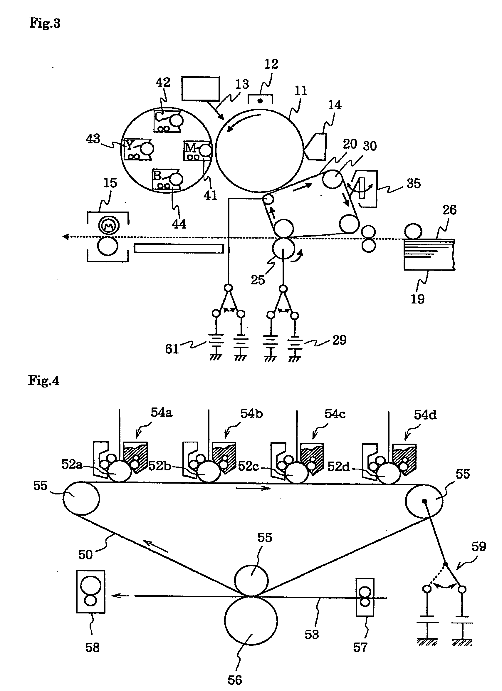
[0033] In the conductive endless belt of the present invention, since the specific polymer material described above is used as the base material, superior strength, in particular, superior folding endurance, can be obtained; since the high molecular weight ionic conductive agent is used, superior electrification properties can be obtained which may not cause any problems commonly observed in the past; and since the fluorinated surfactant is further used, the durability in image output and the transfer efficiency can both be improved. In addition, when the fluorinated resin is used in combination with the base material described above, a belt having superior toner-releasing properties can be formed. Furthermore, when the engage portion is provided so that the drive member and the conductive endless belt engage with each other, a phenomenon can be prevented in which a conductive endless belt wrapped around at least two shafts is gradually shifted in the width direction as the belt rotates. Hence, according to the image forming apparatus of the present invention using the conductive endless belt described above, even when the apparatus is used for a long period of time, no failure occurs at all, and in addition, superior image can be reliably provided.

Problems solved by technology

By the method described above, a relatively compact apparatus can be formed; however, it is very difficult to control the gradation, and as a result, a problem may arise in that a high quality image is not obtained.
By this method, superior image can be obtained; however, since the four drums each provided with an electrification mechanism and a development mechanism are aligned, the apparatus becomes large and expensive.
However, since the electrical resistance of the resistive belt varies with the change in environmental conditions, problems may arise in that the transfer efficiently varies, and / or the thickness and the width of paper adversely influence the transfer performance.
As disadvantages, the increase in transfer voltage may be mentioned which is caused by accumulation of charges in the belt as the transfer is repeatedly performed.
According to this method, a relatively high quality image can be obtained; however, when the recording medium is thick such as a postcard, it is difficult to wind the medium around the transfer drum, and hence the type of recording medium is disadvantageously limited.
In addition, in the resin film belt described above, in order to obtain desired electrification properties required for the member, the adjustment of the conductivity has been generally performed by adding conductive materials such as an electron conductive agent or an ionic conductive agent; however, in electron-conduction belts using an electron conductive agent such as conductive carbon including carbon black filler, the voltage dependence of electrical resistance is large when a voltage is applied, and in particular, when a high voltage is applied, problems such as leakage may occur in some cases.
Furthermore, when a low molecular weight-based antistatic agent is used, for example, various problems occur: the antistatic properties are degraded with time when electricity is supplied, and due to bleedout of a low molecular weight-based material, other constituent elements in contact therewith are contaminated.

Method used


Image

  • Conductive endless belt and image forming apparatus using the same
  • Conductive endless belt and image forming apparatus using the same
  • Conductive endless belt and image forming apparatus using the same

Examples


example 1

[0075] First, 60 parts by weight of a thermoplastic polyamide (PA 12) (trade name: 3024U, manufactured by Ube Industries Ltd.), 30 parts by weight of an acrylonitrile-butadiene-styrene resin (trade name: Cevian V680, manufactured by Daicel Polymer Ltd.), 35 parts by weight of a high molecular weight ionic conductive agent (trade name: Irgastat P18, manufactured by Ciba Specialty Chemicals Inc.), 10 parts by weight of a fluorinated resin (PVdF) (trade name: Neoflon VW410, manufactured by Daikin Industries, Ltd.), 0.4 parts by weight of a fluorinated surfactant (trade name: FTERGENT 100, manufactured by NEOS Co.), and 5 parts by weight of a coloring agent (trade name: ET500W, manufactured by Ishihara Techno Corp.) were mixed together, melted and then kneaded using a biaxial kneader at a predetermined temperature (see Table 2 below; in the following examples and comparative examples, also see Table 2). The compound thus obtained was extrusion molded by a single screw extruder provided ...

examples 2 and 3

[0076] Except that, instead of the fluorinated surfactant (trade name: FTERGENT 100, manufactured by NEOS Co.), a fluorinated surfactant (trade name: FTERGENT 110, manufactured by NEOS Co.) and a fluorinated surfactant (trade name: FTERGENT 300, manufactured by NEOS Co.) were used in Examples 2 and 3, respectively, the conductive endless belts were formed in the same manner as that in Example 1.

examples 4 to 6

[0077] Except that, instead of the fluorinated resin (PVdF) (trade name: Neoflon VW410, manufactured by Daikin Industries, Ltd.), a fluorinated resin (trade name: Neoflon VP825, manufactured by Daikin Industries, Ltd.) was used, the conductive endless belts were formed in Examples 4 to 6 in the same manner as that in Examples 1 to 3, respectively.


PUM


Abstract

A high performance conductive endless belt and an image forming apparatus using the same are provided, the conductive endless belt having superior strength, in particular, superior folding endurance, stable and appropriate electrical resistance even in high voltage application, less voltage dependence of electrical resistance, and superior durability in image output and transfer efficiency. The conductive endless belt is formed by adding a high molecular weight ionic conductive agent and a fluorinated surfactant to a base material selected from the group consisting of (a) a thermoplastic PA, (b) an ABS resin, (c) a thermoplastic POM, (d) a polymer alloy or a polymer blend containing at least two of the above (a) to (c), and (e) a polymer alloy or a polymer blend containing a thermoplastic resin and at least one of the above (a) to (c).

Description

BACKGROUND OF THE INVENTION [0001] 1. Field of the Invention [0002] The present invention relates to a conductive endless belt (hereinafter simply referred to as “belt” in some cases) and an image forming apparatus using the same, the endless belt being used when a toner image is transferred to a recording medium such as paper in an electrostatic recording process performed in an electrostatic recording apparatus or an electrophotographic apparatus such as a copy machine or a printer, the toner image being formed by supplying a developer onto the surface of an image forming member such as a latent image holding member holding a latent image thereon. [0003] 2. Description of the Related Art [0004] Heretofore, in an electrostatic recording process performed in a copy machine, a printer, or the like, printing is performed by the steps of uniformly electrifying the surface of a photosensitive member (latent image holding member), forming an electrostatic latent image by projecting an op...

Claims


Application Information

Patent Timeline
IPC IPC(8): G03G15/01
CPCG03G15/1685G03G2215/0177G03G2215/0119
Inventor SHIMOMURA, TOSHIAKIUENO, YOSHIKAZUAKABANE, HIROSHI
Owner ARCHEM INC
Learn More