

Method for controlling a regeneration valve of a fuel vapor retention system
- Summary
- Abstract
- Description
- Claims
- Application Information
AI Technical Summary
Benefits of technology
Problems solved by technology
Method used
Image

Examples
Embodiment Construction
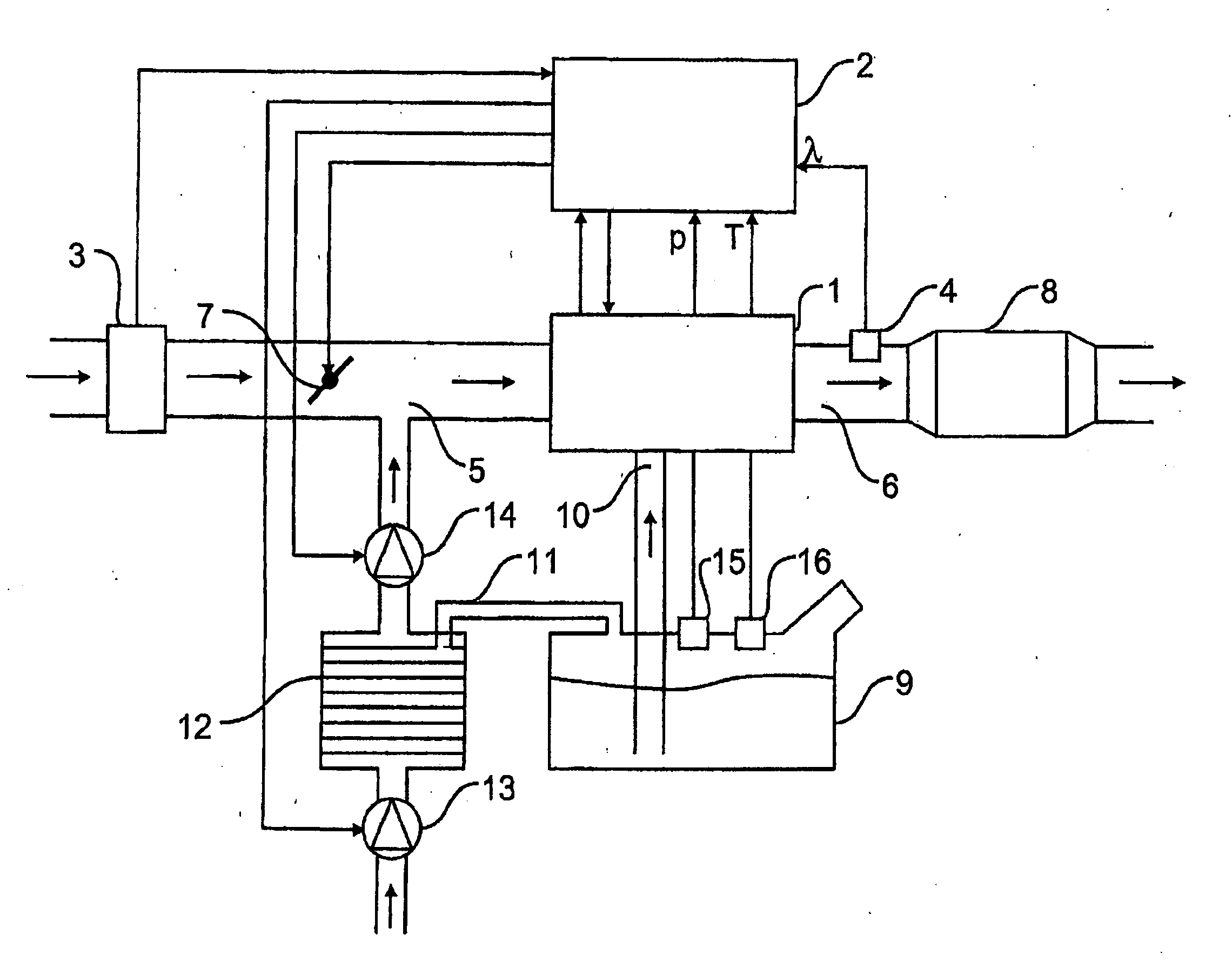
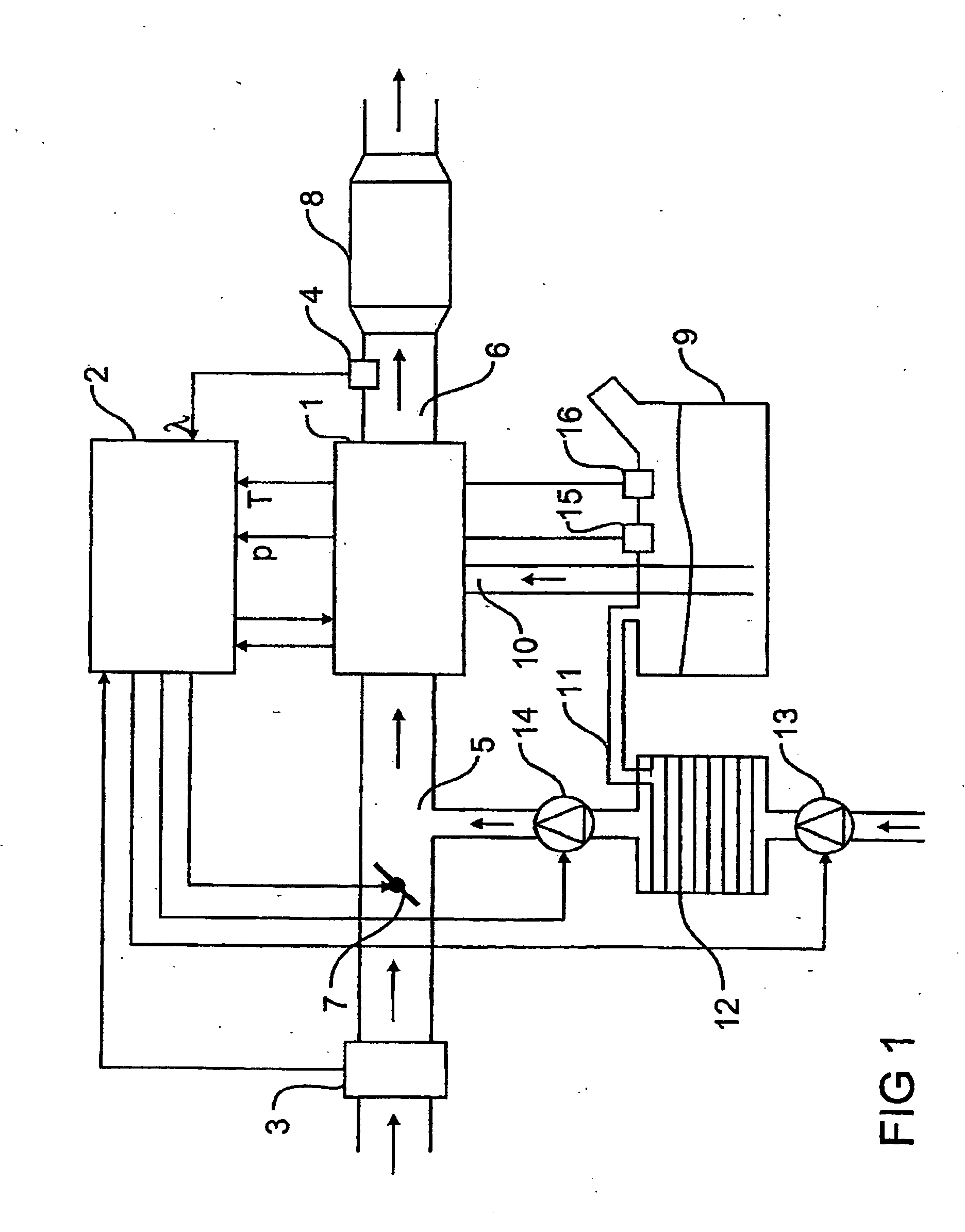
[0033] The representation in FIG. 1 shows an internal combustion engine 1 with an injection system in which case the internal combustion engine 1 is constructed in a conventional way and is therefore only shown diagrammatically.
[0034] The internal combustion engine 1 is controlled by an electronic control unit 2 in which case the control unit 2, for example, specifies the moment of injection as well as the duration of injection of the injection system.
[0035] The control unit 2 evaluates the measuring signals of a mass air flow sensor 3 as well as a lambda sensor 4 as input signals, in which case, the mass air flow sensor 3 is arranged in an intake tract 5 of the internal combustion engine 1 while the lambda sensor 4 is located on the outlet side of the internal combustion engine 1 in an exhaust gas duct 6.
[0036] In addition, a throttle valve 7 is also arranged in the intake tract 5 of the internal combustion engine 1, said throttle valve controlling the mass air flow sensor sucke...
PUM
 Abstract
Description
Claims
Application Information