Laser process to produce drug delivery channel in metal stents

a metal stent and laser technology, applied in metal working devices, other domestic objects, manufacturing tools, etc., can solve the problems of reoccurring constrictions or blockages, exacerbate the occurrence of restenosis or thrombosis, and affect areas of the body not needing treatmen

Inactive Publication Date: 2006-03-16
ABBOTT CARDIOVASCULAR
View PDF44 Cites 30 Cited by
  • Summary
  • Abstract
  • Description
  • Claims
  • Application Information

AI Technical Summary

Benefits of technology

[0022] In a still further aspect of the present invention, the method includes delaying exposing the stent structure to the channel cutting laser beam for a selected period of time after beginning to move the stent relative to the laser beam. This method is advantageous in that it accommodates th...

Problems solved by technology

Although the stents are effective in opening the stenotic lumen, the foreign material and structure of the stents themselves may exacerbate the occurrence of restenosis or thrombosis.
Although PTCA and related procedures aid in alleviating intraluminal constrictions, such constrictions or blockages reoccur in many cases.
As such, one drawback associated with the systemic application of drugs is that areas of t...

Method used


Image

  • Laser process to produce drug delivery channel in metal stents
  • Laser process to produce drug delivery channel in metal stents
  • Laser process to produce drug delivery channel in metal stents

Examples


Embodiment Construction

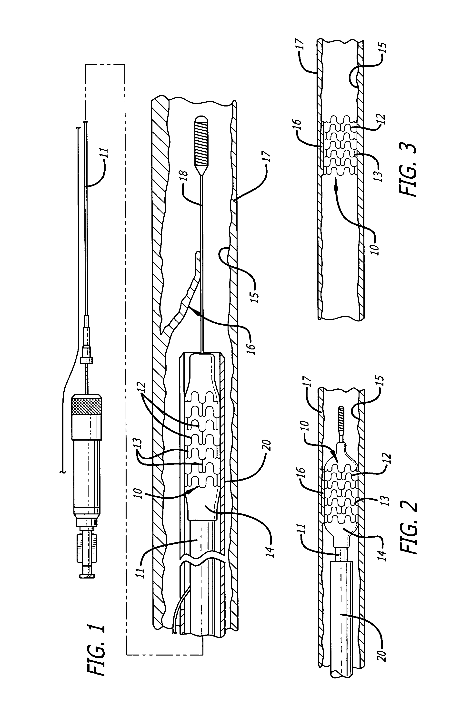
[0039] To assist in understanding the present invention, it is useful to first describe a typical stent, the manner in which it is mounted on a catheter for implantation in a vessel lumen, and a procedure typically used for carrying out the implantation. While one particular stent design is used for illustration, those skilled in the art will understand that the structure and method of the present invention may be applied to any stent design capable of having reservoirs, which may be filled with a therapeutic substance, formed in an outer surface of the stent.

[0040] Referring now to the drawings, and particularly FIG. 1 thereof, there is shown a stent 10 which is mounted onto a delivery catheter 11. The stent 10 is a high precision patterned tubular device. The stent 10 typically comprises a plurality of radially expanded cylindrical elements 12 disposed generally coaxially and interconnected by elements 13 disposed between adjacent cylindrical elements. The delivery catheter 11 ha...


PUM

PropertyMeasurementUnit
Wavelengthaaaaaaaaaa
Lengthaaaaaaaaaa

Abstract

A method for forming a stent and for also forming channels in the outer surface of selected regions of the stent structure. The method includes impinging a laser beam generated by a diode pumped Q-switched pulsed Nd/YAG laser operating at the third harmonic on an outer surface of a stent and controllably machining channels in the outer surface of the stent. The depth of the channels may be controlled by adjusting the power and pulse rate of the laser, and also by adjusting the rate at which the stent moves relative to the laser beam.

Description

BACKGROUND OF THE INVENTION [0001] 1. Field of the Invention [0002] The present invention relates generally to implantable medical devices and to a method for manufacturing implantable medical devices capable of retaining therapeutic materials and dispensing the therapeutic materials to a desired location of a patient's body. More particularly, the present invention relates to an implantable medical device, such as a stent or other intravascular or intraductal medical device, and to a method for forming channels, depots, holes or other indented structures in the structure of the stent or intravascular or intraductal medical device capable of holding a therapeutic material that is dispensed from the stent or other medical device when the stent or other medical device is implanted within a lumen or duct of the patient. [0003] 2. General Background and State of the Art [0004] In a typical percutaneous transluminal coronary angioplasty (PTCA) for compressing lesion plaque against the ar...

Claims


Application Information

Patent Timeline
IPC IPC(8): B23K26/38
CPCA61F2/91B23K2201/06B23K26/08B23K2101/06Y10T83/0341
Inventor SAUNDERS, RICHARD J.
Owner ABBOTT CARDIOVASCULAR
Why Eureka
Try Eureka