Optical image measuring apparatus

a technology of optical image and measuring apparatus, which is applied in the direction of instruments, measurement devices, interferometers, etc., can solve the problems of not automatically setting the sampling frequency of interference light, hard to shorten the measurement time in view of measurement fundamentals, and difficult to actually use the apparatus in fields that require a high resolution image, etc., to achieve high precision, and easy sampling of interference light

Inactive Publication Date: 2006-03-16
KK TOPCON
View PDF6 Cites 38 Cited by
  • Summary
  • Abstract
  • Description
  • Claims
  • Application Information

AI Technical Summary

Benefits of technology

[0039] According to the first aspect of the present invention, the frequency for the intensity modulation of the light beam which is performed by the light beam outputting means is synchronized with the frequency of the interference light. The frequency of vibration of the reference object which is caused by the vibrating means is synchronized with the frequency of the interference light and the amplitude of the vibration is set to be equal to or smaller than the wavelength of the interference light. The two polarized light components extracted by the extracting means are detected by the set of detecting means. The signal intensity of the interference light or the phase thereof is calculated based on the result obtained by detection to form the image of the object to be measured. Therefore, the interference light, in particular, an alternating current component thereof can be detected by only the set of detecting means, that is, the two detecting means to form the image of the object to be measured. In addition, the frequency for the intensity modulation of the light beam and the frequency and amplitude of vibration of the reference object can be automatically set, so it is possible to easily sample the interference light with high precision.
[0040] According to the second aspect of the pre

Problems solved by technology

In addition, it is hard to shorten a measurement time in view of measurement fundamentals.
Therefore, it is supposedly hard to actually use the apparatus in fields that require a high resolution image, such as a medical field and an industrial field.
However, according to the optical image measuring apparatus described in JP 2001-330558 A (claims, specification paragraphs to , and FIG. 1), the sampling frequency of the interference light is not automatically set, so the setting takes an effort.
In addi

Method used


Image

  • Optical image measuring apparatus
  • Optical image measuring apparatus
  • Optical image measuring apparatus

Examples


first embodiment

[Structure of Apparatus]

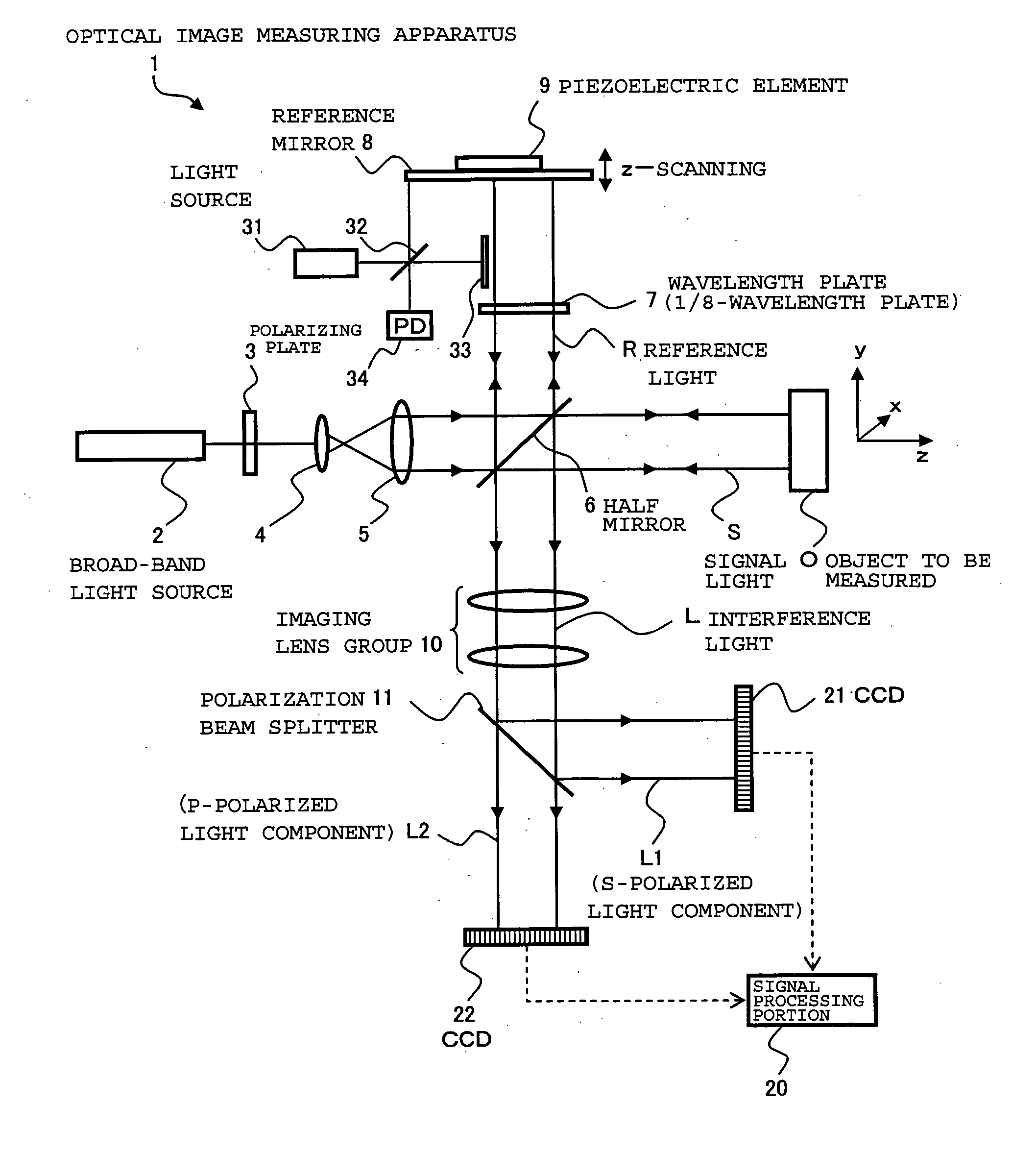
[0052] First, an optical image measuring apparatus according to the first embodiment of the present invention will be described in detail with reference to FIGS. 1 and 2. FIG. 1 shows a schematic structure of (mainly) an optical system of the optical image measuring apparatus according to this embodiment. FIG. 2 shows a structure of a control system of the optical image measuring apparatus according to this embodiment.

[Structure of Optical System]

[0053] The optical image measuring apparatus in this embodiment is an apparatus available to measure a sectional image and a surface image of an object to be measured, for example, in the medical field and the industrial field. Here, the object to be measured is an object which is made of a scattering medium such as a human eye, for example, in the medical field.

[0054] The optical image measuring apparatus 1 in this embodiment shown in FIG. 1 includes a broad-band light source 2 for outputting a low-coherent ligh...

modified example

[0116] In the above-mentioned structure, the z-scanning of the reference mirror 8 using the piezoelectric element 9 is performed to apply the frequency shift to the reference light R. A frequency shifter (such as an optoelectronic modulator or an acoustooptic modulator) may be provided on the optical path of the reference light R. A structural example in such a case will be described later (see FIG. 4). The frequency shifter may be on the optical path of the signal light S. This is because it is only necessary that the frequency of the signal light S and the frequency of the reference light R at the time of superimposition be shifted relative to each other in the image measurement according to the present invention.

[0117] In the above-mentioned structure, the light beam from the broad-band light source 2 is converted to the linearly polarized light and then divided into the signal light S and the reference light R. Each of the signal light S and the reference light R may be convert...

second embodiment

[0134] Subsequently, an optical image measuring apparatus according to a second embodiment of the present invention will be described. In this embodiment, as described above, the interference light L is sampled using shutters.

[Structure of Apparatus]

[0135] First, the optical image measuring apparatus according to this embodiment will be described. FIG. 5 shows (mainly) an optical system of the optical image measuring apparatus according to this embodiment and FIG. 6 shows a control system thereof. Hereinafter, the same references are provided to the same constituent portions as those in the first embodiment.

[Structure of Optical System]

[0136] As shown in FIG. 5, an optical image measuring apparatus 100 according to this embodiment includes the broad-band light source 2 (light source), the lenses 4 and 5, the half mirror 6 (dividing means and superimposing means), the reference mirror 8 (reference object), and the piezoelectric element 9 (vibrating means). The light source 2 is c...


PUM


Abstract

Provided is an optical image measuring apparatus capable of effectively receiving interference light, particularly an alternating current component thereof using a smaller number of photo sensors. The optical image measuring apparatus includes a polarizing plate for converting a light beam from a broad-band light source to linearly polarized light, a half mirror for dividing the light beam into signal light and reference light, a piezoelectric element for vibrating a reference mirror, a wavelength plate for converting the reference light to circularly polarized light, a polarization beam splitter for extracting two different polarized light components from interference light produced from the signal light and the reference light which are superimposed on each other by the half mirror, CCDs for detecting the two different polarized light components, and a signal processing portion for producing an image of an object to be measured based on the detected polarized light components. A frequency for intensity modulation of the light beam is synchronized with a beat frequency of the interference light. A frequency of vibration of the reference mirror is synchronized with the beat frequency of the interference light and an amplitude of vibration thereof is set to be equal to or smaller than a wavelength of the interference light.

Description

BACKGROUND OF THE INVENTION [0001] 1. Field of the Invention [0002] The present invention relates to an optical image measuring apparatus for applying a light beam to an object to be measured, particularly a light scattering medium, and for measuring a surface form or inner form of the object to be measured by receiving a reflected light beam or a transmitted light beam to produce an image of a measured form. In particular, the present invention relates to an optical image measuring apparatus for measuring the surface form or inner form of the object to be measured by using an optical heterodyne detection method to produce the image of the measured form. [0003] 2. Description of the Related Art [0004] In recent years, attention has been given to an optical image measuring technique for producing an image of a surface or inner portion of an object to be measured using a laser light source or the like. This optical image measuring technique is not hazardous to human bodies in contrast...

Claims


Application Information

Patent Timeline
IPC IPC(8): G01B11/02
CPCG01B11/2441G01B9/02003G01B9/02027G01B2290/45G01B9/02014G01B9/02069G01B2290/70G01B9/02091
Inventor AKIBA, MASAHIROCHAN, KINPUIFUKUMA, YASUFUMIOTSUKA, HIROYUKITSUKADA, HISASHIYUMIKAKE, KAZUHIKO
Owner KK TOPCON
Why Eureka
Try Eureka