Moving vacuum chamber stage with air bearing and differentially pumped grooves

a vacuum chamber and air bearing technology, applied in the field of equipment, can solve the problems of limiting optical techniques, difficulty in achieving the required precision, and technical difficulties in using air bearing stages in vacuum, and achieve the effects of improving the structural loop, reducing the requirements of vacuum pumping and pumping down time, and improving the structural loop

Inactive Publication Date: 2006-03-23
NEW WAY MACHINE COMPONENTS
View PDF18 Cites 64 Cited by
  • Summary
  • Abstract
  • Description
  • Claims
  • Application Information

AI Technical Summary

Benefits of technology

[0007] To achieve the above and other objects, an important design feature in this invention is that instead of trying to build a stage inside a vacuum chamber or reach through a chamber wall, the stage itself becomes the vacuum chamber. Such a stage is called a vacuum chamber stage (VCS). By having the primary or only vacuum chamber completely contained inside the moving stage, all motion systems can exist outside of the vacuum. Because the vacuum chamber size can be reduced to little more than the volume of the substrate, the vacuum pumping requirements and pump down times are dramatically reduced, and the requirement for a large conventional vacuum chamber is eliminated. At the same time, th...

Problems solved by technology

A point has been reached where optical techniques are limiting because of the width of the wavelength of light.
There are technical difficulties in attempting to use air-bearing stages in vacuum, as the escaping air increases the pressure in the vacuum chamber.
Use of rolling element or plane bearing technology has been used, but it is difficult to achieve the required precision.
The difficulty here is that the stages quickly become very large to provide the ...

Method used


Image

  • Moving vacuum chamber stage with air bearing and differentially pumped grooves
  • Moving vacuum chamber stage with air bearing and differentially pumped grooves
  • Moving vacuum chamber stage with air bearing and differentially pumped grooves

Examples


Embodiment Construction

[0014] Preferred embodiments of the present invention will now be set forth in detail with reference to the drawings.

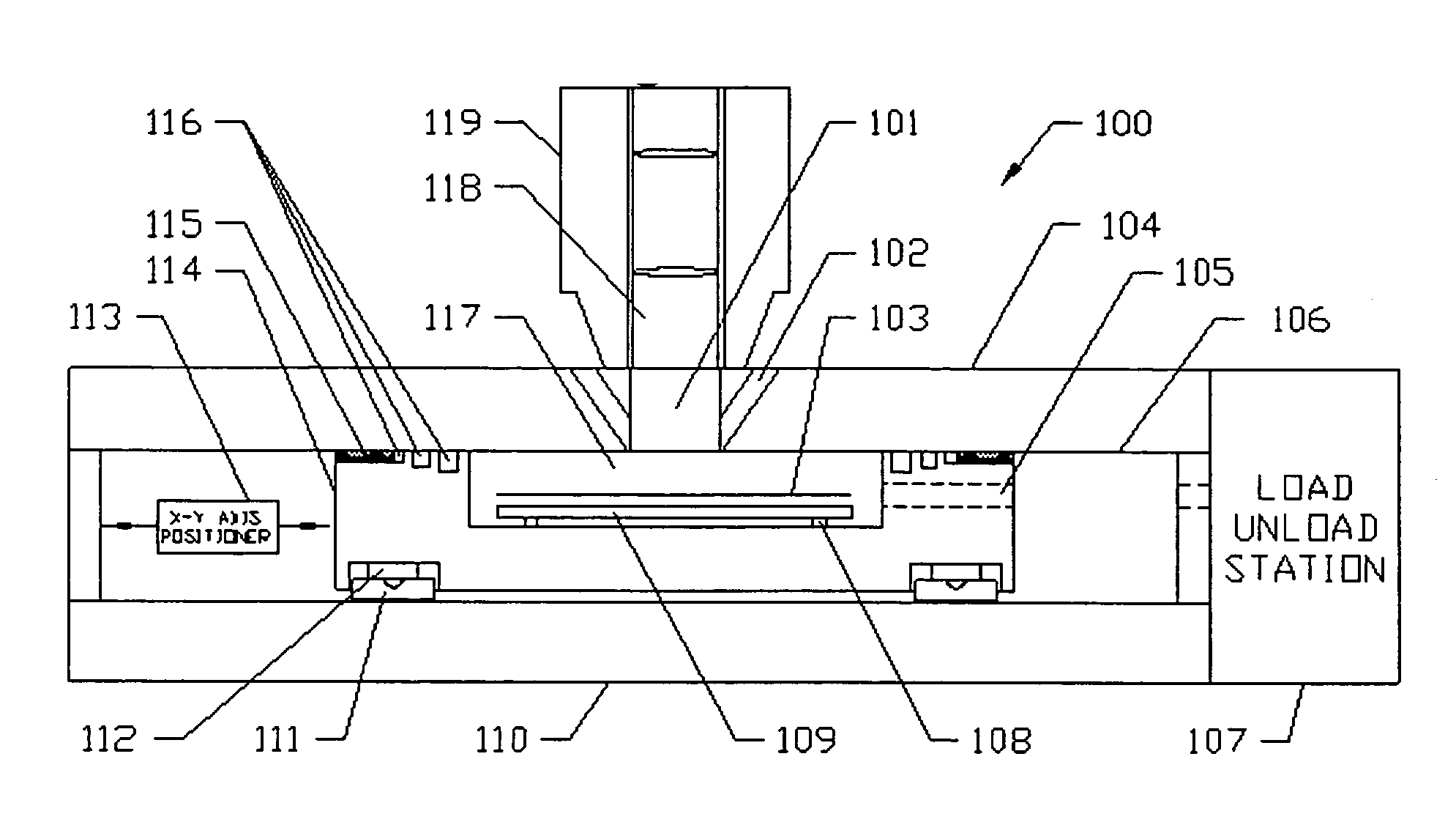
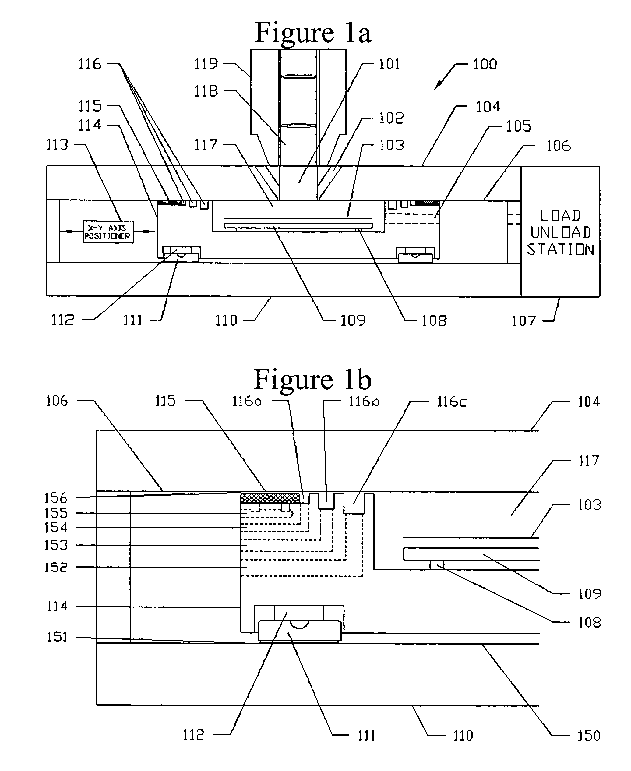
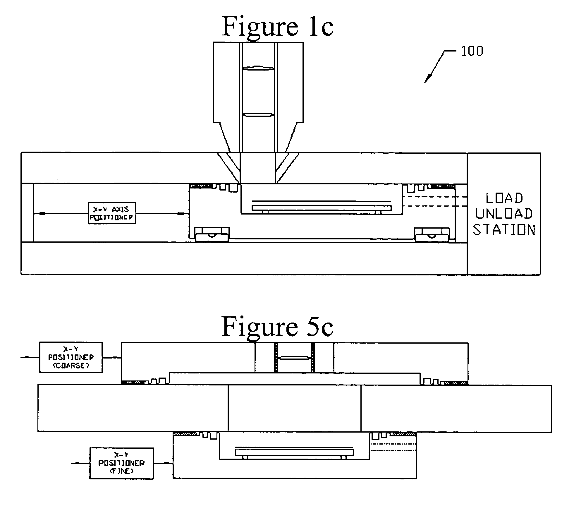
[0015]FIG. 1a is a side view sectional schematic of a vacuum chamber stage 100 used for precision positioning of the semiconductor wafer or substrate 103 while the substrate is maintained in a vacuum chamber 117. The object of the apparatus is to expose the substrate to some sort of a manufacturing, processing or inspection for the purpose of manufacturing microelectronics circuits there on. Typically the substrate is exposed to some sort of radiation; examples of the many species of radiation would include but are not limited to Ions, x-rays, ultraviolet or extreme ultraviolet, electron beams, DUV (deep ultraviolet), extreme ultraviolet (soft x-rays) and visible light. Often this radiation needs to be conditioned by such devices as analyzers, magnets, mirrors or optics. This conditioning of radiation in this illustration is provided for in the area indicated by 119....


PUM


Abstract

A stage for processing a substrate, especially useful for vacuum applications, has a recess just large enough to hold a substantially flat substrate and a chuck or holder but not much more. The perimeter of the recessed side has an air bearing surface separated from the recess by differentially pumped groves and seal lands. The air bearing lands are urged against a reference plate guide surface and the seal lands being substantially coplanar create a resistance to flow between the groves and recess, on the other side of the base reference plate mounts the radiation source. The VCS may operate in a vacuum environment itself, or in another preferred embodiment, it provides the possibility for multiple stages moving between process or inspection steps within the same tool or process sequence.

Description

REFERENCE TO RELATED APPLICATIONS [0001] The present application claims the benefit of U.S. Provisional Patent Application No. 60 / 602,339, filed Aug. 18, 2004, and U.S. Provisional Patent Application No. 60 / 697,973, filed Jul. 12, 2005, whose disclosures are hereby incorporated by reference in their entireties into the present disclosure.FIELD OF THE INVENTION [0002] This invention relates generally to equipment used in the manufacturing of semiconductor devices and masks and more particularly to equipment used in vacuum processes. Applications are anticipated in areas including, but not limited to, ion implant and milling, deposition, etch, ash, clean, lithography and inspection. DESCRIPTION OF RELATED ART [0003] Because of the shrinking feature sizes in semiconductor wafers, greater degrees of precision are required in the stages used to provide the necessary motions. Because air-bearing stages allow for higher precision, they are commonly used to pattern and inspect semiconductor...

Claims


Application Information

Patent Timeline
IPC IPC(8): B25B11/00B65B31/04B05D3/00A47J41/00
CPCB05D3/0493H01J2237/3175F16C29/025F16C32/0618F16C33/748F16C2300/62F16J15/40F16J15/443G03F7/70716G03F7/70816G03F7/70841H01L21/67126H01L21/67784H01L21/68H01L21/68714H01J37/20H01J2237/166H01J2237/2006H01J2237/202H01J2237/28H01J2237/31701B25B11/005
Inventor DEVITT, ANDREW J.
Owner NEW WAY MACHINE COMPONENTS
Why Eureka
Try Eureka