Method and driving circuit for driving liquid crystal display, and portable electronic device

Inactive Publication Date: 2006-03-23
RENESAS ELECTRONICS CORP
View PDF14 Cites 16 Cited by
  • Summary
  • Abstract
  • Description
  • Claims
  • Application Information

AI Technical Summary

Benefits of technology

[0028] In view of the above, it is an object of the present invention to provide a method and a driving circuit for driving an LCD, being capable of reducing power consumption, decreasing a packaging area or a number of packaged parts and pr

Problems solved by technology

Furthermore, it is inevitably necessary to make small and lightweight the portable electronic devices being driven by the battery or the like such as the notebook computer, palm-size computer, pocket computer, PDA, portable cellular phone, PHS, or the like.
This produces a bottleneck in reducing power consumption in the above portable electronic dev

Method used


Image

  • Method and driving circuit for driving liquid crystal display, and portable electronic device
  • Method and driving circuit for driving liquid crystal display, and portable electronic device
  • Method and driving circuit for driving liquid crystal display, and portable electronic device

Examples


first embodiment

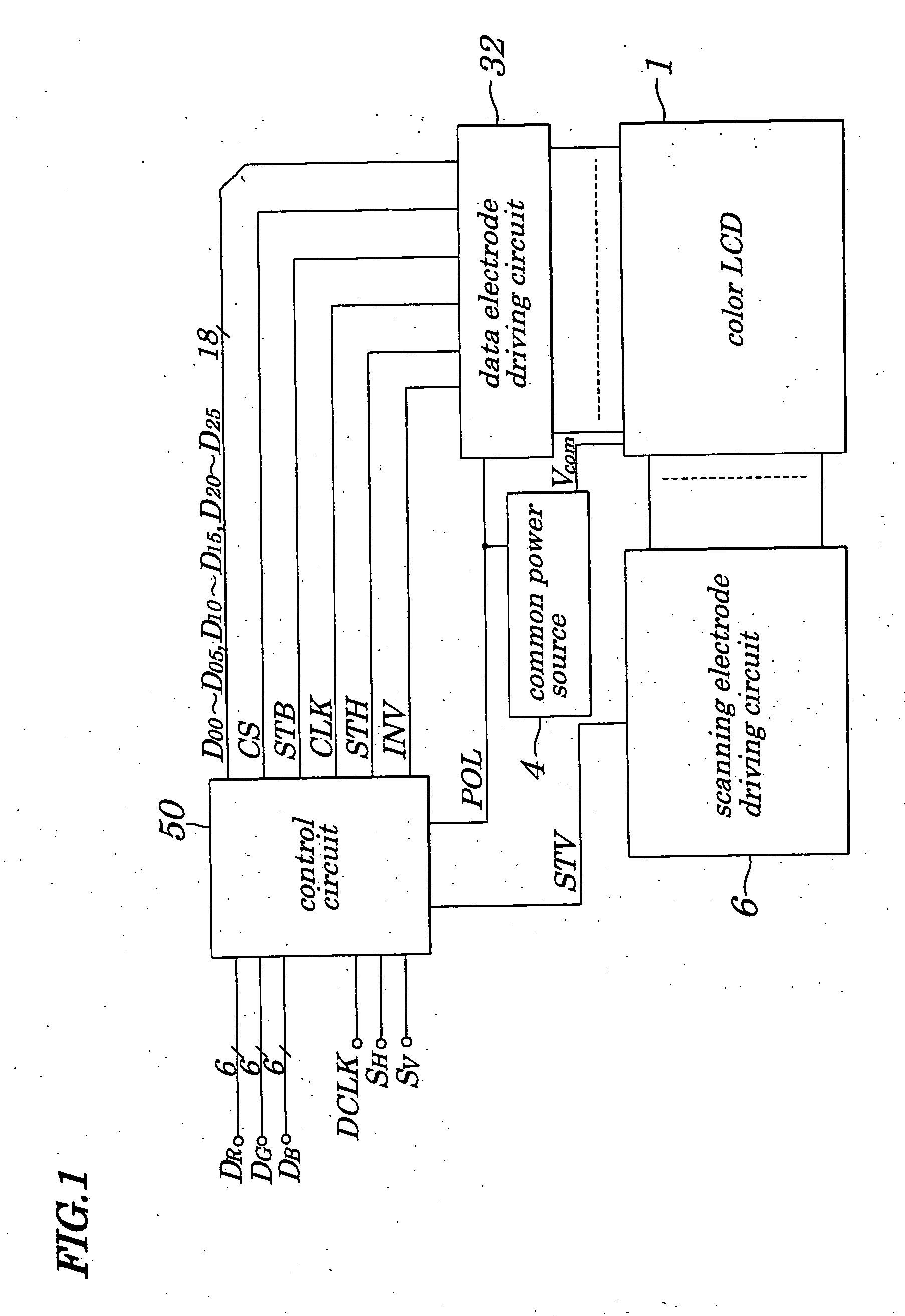
[0082]FIG. 1 is a schematic block diagram for showing configurations of a driving circuit for a color LCD 1 according to a first embodiment of the present invention. In FIG. 1, same reference numbers are assigned to components having the same functions as those in the conventional example in FIG. 20 and their descriptions are omitted accordingly. In the driving circuit for the color LCD 1 shown in FIG. 1, instead of a control circuit 2 and a data electrode driving circuit 5 shown in FIG. 20, a control circuit 50 and a data electrode driving circuit 32 are newly placed and a gray scale power source 3 shown in FIG. 20 is removed. In the first embodiment, as in the case of the conventional example, it is presumed that the color LCD 1 provides 176×220 pixel resolution and, therefore, the number of dot pixels is 528×220.

[0083] The control circuit 50 is made up of, for example, ASICs and has, in addition to functions provided by the control circuit 2 in FIG. 20, functions of producing a ...

second embodiment

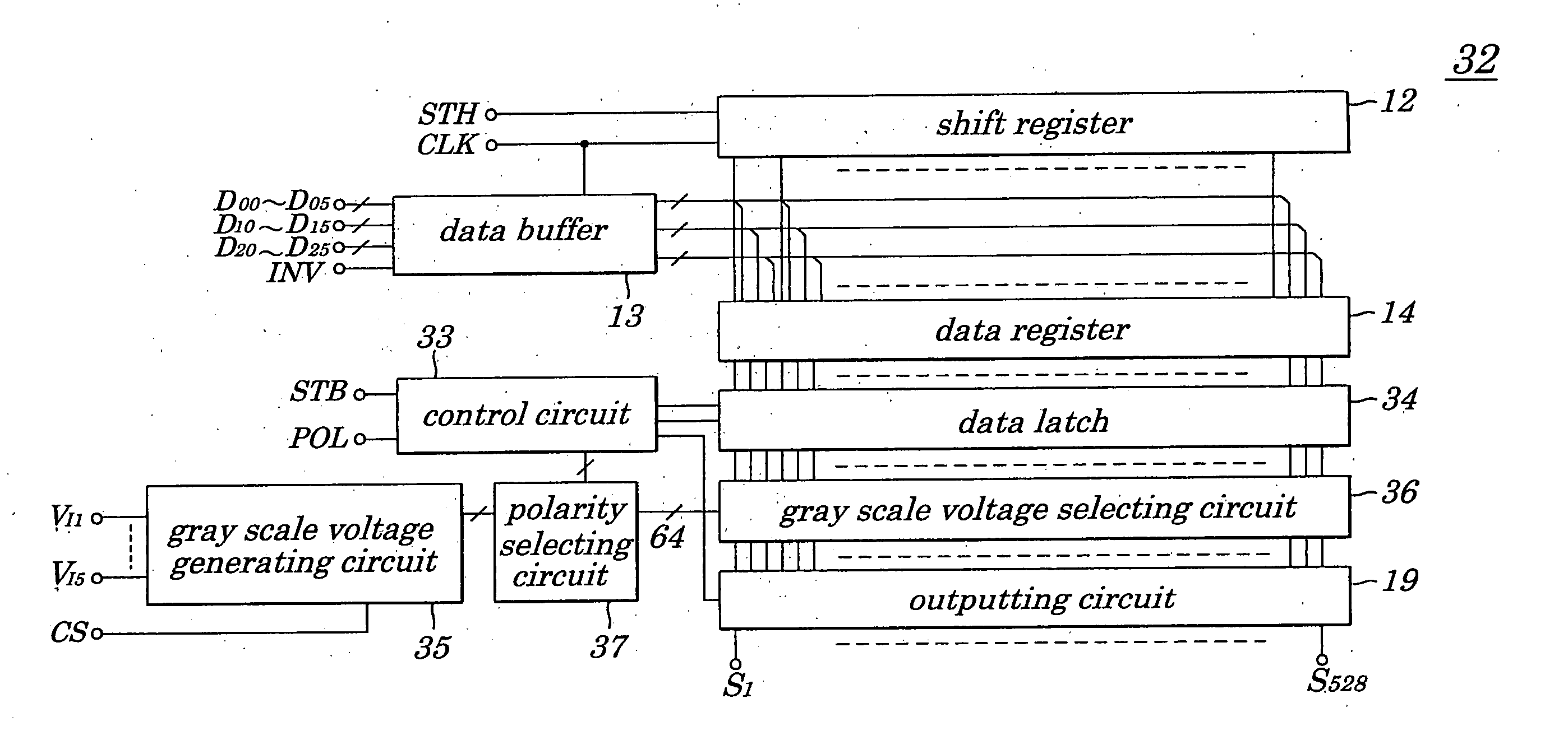
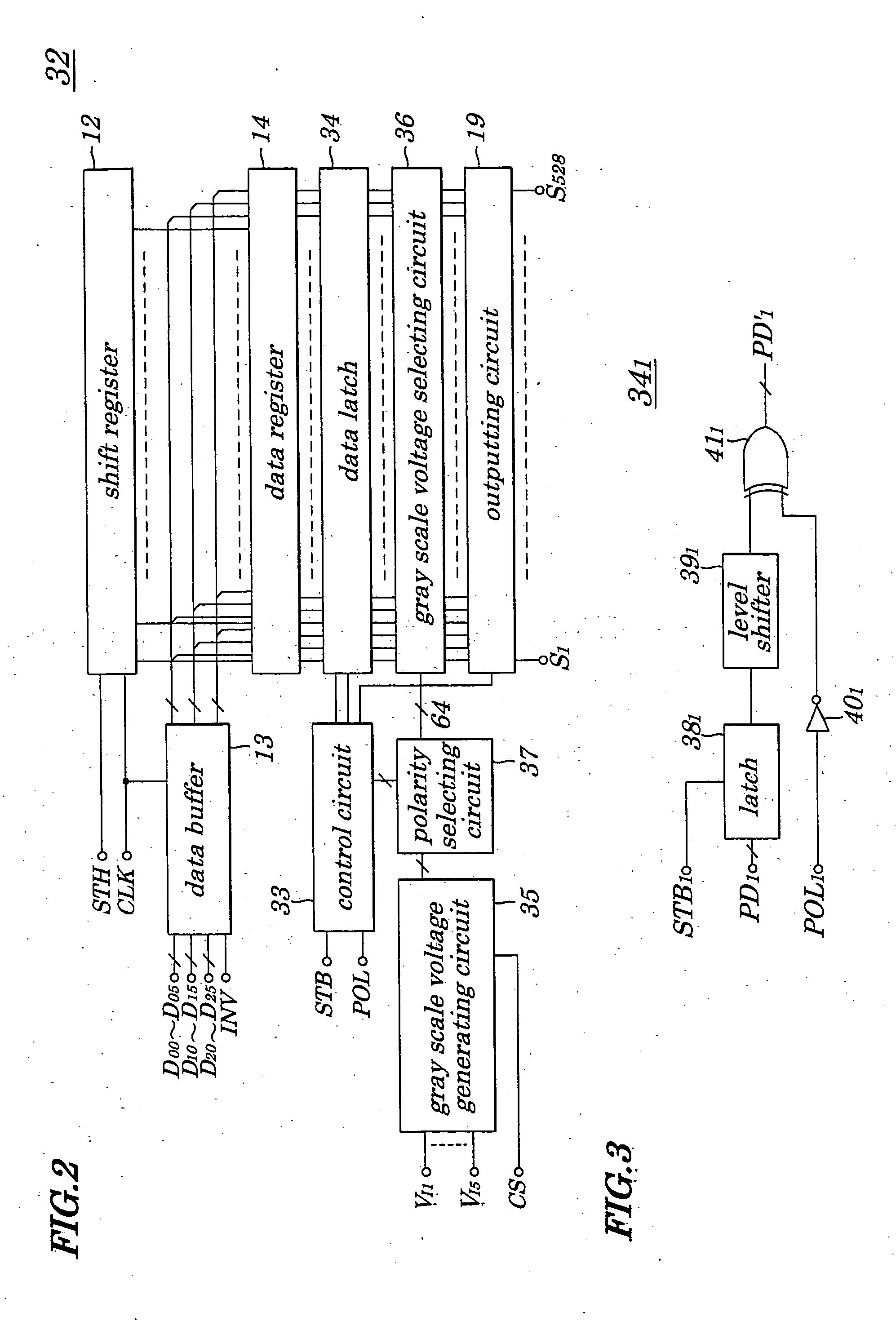
[0104]FIG. 8 is a schematic block diagram for showing configurations of a driving circuit for a color LCD 1 according to a second embodiment of the present invention. In FIG. 8, same reference numbers are assigned to components having same functions as those in FIG. 1 and their descriptions are omitted accordingly. In the driving circuit for the color LCD 1 shown in FIG. 8, instead of a control circuit 50 and a data electrode driving circuit 32 shown in FIG. 1, a control circuit 51 and a data electrode driving circuit 52 are newly placed. In the second embodiment, as in the case of the first embodiment, it is presumed that the color LCD 1 provides 176×220 pixel resolution. Therefore, the number of dot pixels is 528×220. The control circuit 51 is made up of, for example, ASICs and has, instead of functions to produce a chip select signal CS provided in the first embodiment, functions of producing an amplifier control signal VS and feeding it to the data electrode driving circuit 52. ...

third embodiment

[0127]FIG. 16 is a schematic block diagram for showing configurations of a driving circuit for a color LCD 1 according to a third embodiment of the present invention. In FIG. 16, same reference numbers are assigned to components having same functions as those in FIG. 1 and their descriptions are omitted accordingly. In the driving circuit for the color LCD 1 shown in FIG. 16, instead of a data electrode driving circuit 32 shown in FIG. 1, a data electrode driving circuit 82 is newly provided. In the third embodiment, as in a case of the second embodiment, it is presumed that the color LCD 1 provides 176×220 pixel resolution and therefore the number of dot pixels is 528×220.

[0128]FIG. 17 is a schematic block diagram for showing configurations of a data electrode driving circuit employed in the driving circuit for the color LCD 1 according to the third embodiment of the present invention. In FIG. 17, same reference numbers are assigned to components having same functions as those in ...


PUM


Abstract

A method for driving a liquid crystal display capable of reducing power consumption, decreasing a packaging area or a number of packaged parts, and providing an image of high quality. Digital video data is output, with or without data being inverted, based on a polarity signal being inverted in every one horizontal sync period or in every one vertical sync period. A plurality of gray scale voltages is selected having either a positive or negative voltage. Any one of the plural gray scale voltages is selected based on digital video data, with or without inversion of a polarity of gray scale voltages. The selected one gray scale voltage is applied as a data signal to a corresponding data electrode.

Description

CROSS REFERENCE TO RELATED APPLICATIONS [0001] This application is a division of co-pending application Ser. No. 10 / 046,155, filed on Jan. 16, 2002, the entire contents of which are hereby incorporated by reference.BACKGROUND OF THE INVENTION [0002] 1. Field of the Invention [0003] The present invention relates to a method and a driving circuit for driving a liquid crystal display (LCD), and portable electronic devices employing the driving circuit and more particularly to the method and the driving circuit for driving the LCD used as a display section having a comparatively small display screen of portable electronic devices such as a notebook computer, palm-size computer, pocket computer, personal digital assistance (PDA), portable cellular phone, personal handy-phone system (PHS) or a like and to the portable electronic devices equipped with such the driving circuit for the LCD. [0004] The present application claims priority of Japanese Patent Application No. 2001-008322 filed on...

Claims


Application Information

Patent Timeline
IPC IPC(8): G09G3/36G09G3/20G02F1/133
CPCG09G3/3611G09G3/3614G09G3/3685G09G2330/021G09G2310/027G09G2320/0247G09G3/3696G09G3/36
Inventor HASHIMOTO, YOSHIHARU
Owner RENESAS ELECTRONICS CORP
Why Eureka
Try Eureka