High efficiency low pollution hybrid brayton cycle combustor

a combustor and high efficiency technology, applied in the direction of machines/engines, efficient propulsion technologies, light and heating apparatus, etc., can solve the problems of limited general adoption of such engines, inability of such engines to meet sudden demand and/or maintain a constant working temperature or pressure, and inability to control such engines inefficiently, so as to achieve clean, efficient, pollution-free power

Inactive Publication Date: 2006-03-30
GINTER J LYELL +1
View PDF14 Cites 22 Cited by
  • Summary
  • Abstract
  • Description
  • Claims
  • Application Information

AI Technical Summary

Benefits of technology

[0020] It is also an object of this invention to completely control the temperature of combustion within a combustor through the employment of the latent heat of vaporization of water without the necessity to mechanically compress excess (dilution) air for cooling.
[0044] The use of this new cycle results in increased horsepower at a lower rpm, slow idle, fast acceleration and combustion of up to 95% of the compressed air at low rpm.

Problems solved by technology

In these devices, temperature control is usually the result of feeding large quantities of excess compressed air.
Each of these prior engines has encountered difficulties which limit their general adoption as a power source for the operation of prime movers.
Among these difficulties have been the inability of such an engine to meet sudden demand and / or to maintain a constant working temperature or pressure as may be required for efficient operation of such an engine.
Furthermore, control of such engines has been inefficient, and the ability of the gas generator to maintain itself in standby condition has been wholly inadequate.
In all practical applied engine configurations the requirement for cooling the confining walls of the work cylinders has resulted in loss of efficiency and a number of other disadvantages previously inherent in internal combustion engines.

Method used


Image

  • High efficiency low pollution hybrid brayton cycle combustor
  • High efficiency low pollution hybrid brayton cycle combustor
  • High efficiency low pollution hybrid brayton cycle combustor

Examples


Embodiment Construction

[0056] A. Basic Configuration of the Present System

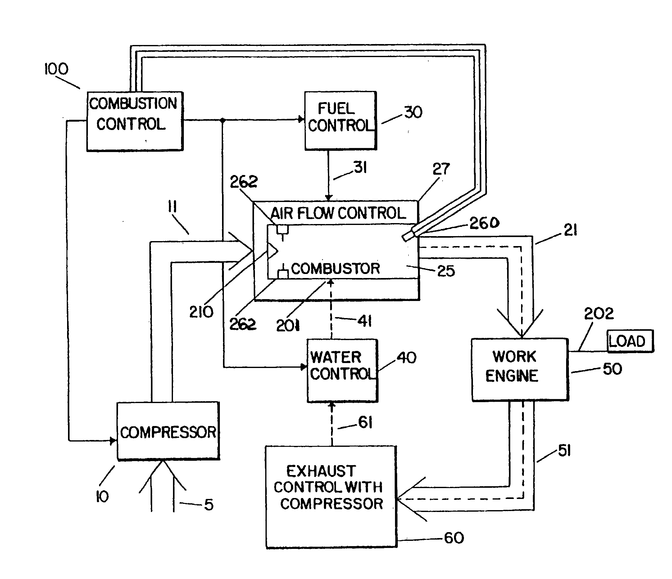
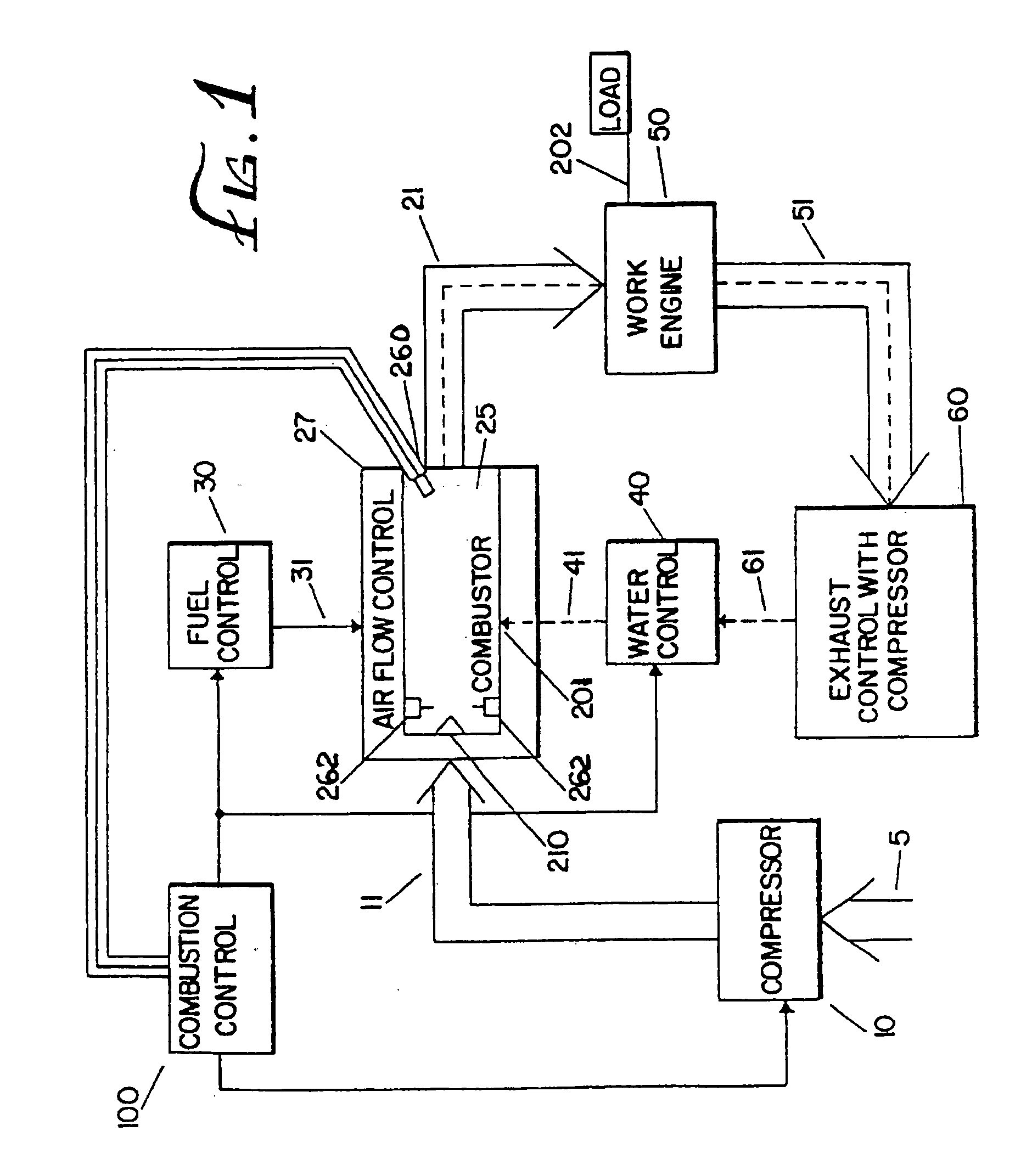
[0057] Referring now to FIG. 1, there is shown schematically a gas turbine engine embodying the teachings of the present invention. Ambient air 5 is compressed by compressor 10 to a desired pressure resulting in compressed air 11. In a preferred embodiment, compressor 10 is a typical well-known two or three stage compressor, and the ambient air 5 is compressed to a pressure greater than about four (4) atmospheres, and preferably 10 to 30 atmospheres. The temperature of the compressed air depends on the compression ratio. At a compression ratio of 30:1 the compressed air temperature is approximately 1424° R (964° F.).

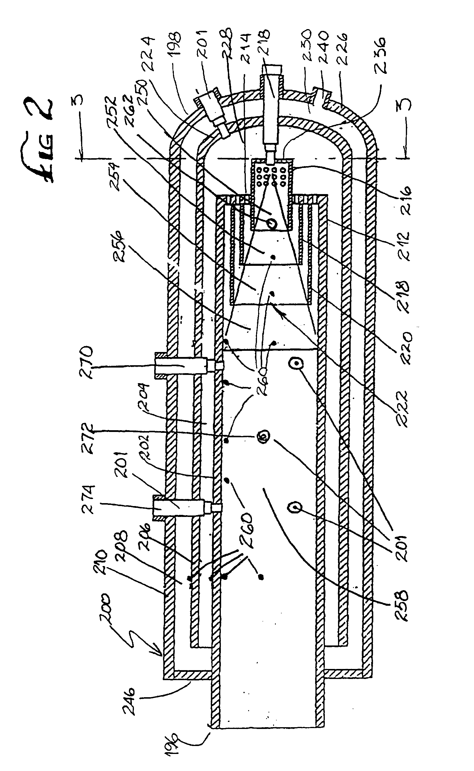
[0058] The flow of the compressed air 11 is controlled by an air flow controller 27 to a combustor 25. Combustors are well-known in the art. However, in the present invention, the compressed air 11 is supplied in a staged, circumferential manner by air flow control 27 to the combustor 200 shown in FIG. 2 and more fully...


PUM


Abstract

A power generating system and method operating at high pressure and utilizing a working fluid consisting of a mixture of compressed non-flammable air components, fuel combustion products and steam. The working fluid is substantially free of CO and NOx. Fuel and compressed air at an elevated temperature and at a constant pressure are delivered to a combustion chamber, the amount of air being chosen so that at least about 90% of the oxygen in the air is consumed during combustion. The quantity of air and fuel supplied to the combustion chamber may be varied provided a constant fuel to air ratio is maintained. Superheated water is delivered under pressure to the combustion chamber, and is converted substantially instantaneously to steam. The quantity of water delivered is controlled such that the latent heat of vaporization of the water maintains the temperature of the working fluid at a desired level. Heat may be transferred from the working fluid exiting the work engine to the water to heat the water to the desired temperature for delivery to the combustion chamber. The quantity, temperature and pressure of the air, fuel and water introduced in to the combustion chamber are independently controllable. A zoned burner may be employed in which a portion of the compressed air may be mixed with the fuel in a first zone prior to ignition, with the remaining compressed air being added at one or more locations downstream of the point of ignition.

Description

PRIORITY INFORMATION [0001] The present application is a continuation of U.S. application Ser. No. 10 / 713,899, filed Sep. 12, 2003, which is a conversion of U.S. Provisional Application 60 / 418,989, filed Oct. 15, 2002 and is a continuation in-part of U.S. application Ser. No. 10 / 161,159, filed May 30, 2002, now U.S. Pat. No. 6,564,556, which is a continuation of U.S. application Ser. No. 09 / 645,986, filed Oct. 27, 2000, now abandoned, which is a divisional of U.S. application Ser. No. 09 / 042,231, filed Mar. 11, 1998, now U.S. Pat. No. 6,289,666, which is a continuation-in-part of U.S. application Ser. No. 08 / 232,047, filed Apr. 26, 1994, now U.S. Pat. No. 5,743,080, which is a continuation-in-part of U.S. application Ser. No. 07 / 967,289, filed Oct. 27, 1992, now U.S. Pat. No. 5,617,719, all of which are hereby incorporated by reference.BACKGROUND OF THE INVENTION [0002] 1. Field of the Invention [0003] The present invention is directed to a vapor-air steam engine which operates at h...

Claims


Application Information

Patent Timeline
Patent Type & Authority Applications(United States)
IPC IPC(8): F02C3/30F01K21/04F23J15/00F23L7/00
CPCF01K21/047F02C3/30F05D2270/082F05D2270/083F23J15/003Y02E20/344F23L2900/07002F23L2900/07008F23L2900/07009Y02T50/672Y02T50/677F23L7/00Y02T50/60
Inventor GINTER, J. LYELLGINTER, GARY
Owner GINTER J LYELL
Why Eureka
Try Eureka