Bonding apparatus using conductive material

a technology of conductive materials and bonding devices, which is applied in the direction of metal working equipment, soldering equipment, manufacturing tools, etc., can solve the problems of reducing the amount of solder supplied, and affecting the supply of solder

Inactive Publication Date: 2006-03-30
SAE MAGNETICS H K LTD 50
View PDF5 Cites 12 Cited by
  • Summary
  • Abstract
  • Description
  • Claims
  • Application Information

AI Technical Summary

Benefits of technology

[0011] The present invention is made in consideration of the above-mentioned problems and an object of the present invention is to provide a bonding apparatus in which molten co

Problems solved by technology

If such adhesion of the solder occurs, the inner diameter of the nozzle is decreased, with the result that a solder supplying amoun

Method used


Image

  • Bonding apparatus using conductive material
  • Bonding apparatus using conductive material
  • Bonding apparatus using conductive material

Examples


Embodiment Construction

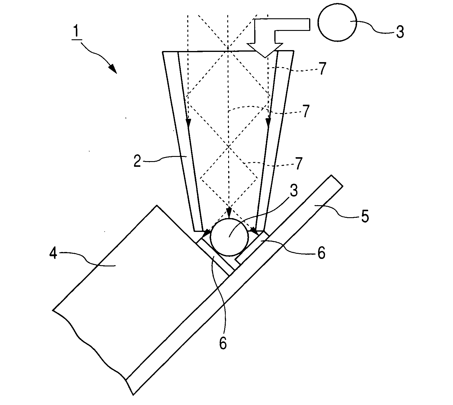
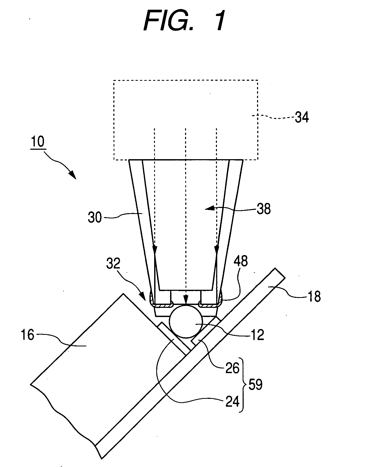
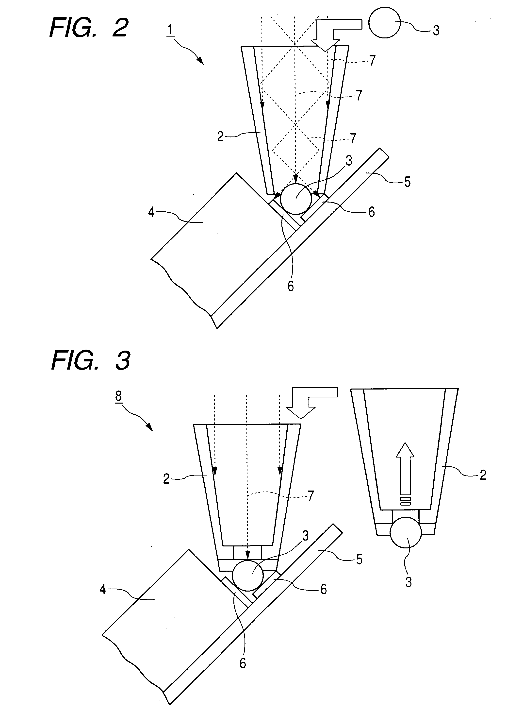
[0023] Now, a preferred concrete embodiment of a solder ball bonding apparatus according to the present invention will be fully explained with reference to the accompanying drawings. In the embodiment, solder is used as an example of the conductive material. FIG. 1 is an explanatory view showing a condition that a solder ball is melted on an electrode area by using a solder ball bonding apparatus according to an embodiment of the present invention.

[0024] As shown in FIG. 1, a solder ball bonding apparatus 10 according to the illustrated embodiment can be shifted reciprocally, by shifting means (not shown), between a supplying device (not shown) for supplying a solder ball 12 and magnetic head constituting parts which are objects to be bonded. Incidentally, the magnetic head constituting parts described here are a slider 16 into which GMR elements and the like are embedded, and a flexor 18 for supporting the slider 16.

[0025] By the way, in the illustrated embodiment, slider side el...


PUM

PropertyMeasurementUnit
Thicknessaaaaaaaaaa
Electrical conductoraaaaaaaaaa
Wettabilityaaaaaaaaaa

Abstract

The present invention provides a bonding apparatus in which solder is conveyed onto a predetermined electrode, and the solder is melted by irradiation of a laser beam and is bonded to the electrode and has an object to prevent the solder from adhering to a solder conveying system of the apparatus. To achieve the above object, in the bonding apparatus, a film having low wettability to the solder and having a predetermined thickness such as a DLC film is coated on a region and a neighborhood of a solder holding and conveying member, which is contacted with the solder.

Description

[0001] This application claims priority from Japanese Patent Application No. 2004-282924 filed on Sep. 29, 2004, which is hereby incorporated by reference herein. BACKGROUND OF THE INVENTION [0002] 1. Field of the Invention [0003] The present invention relates to a bonding apparatus using conductive material such as solder and, more particularly, it relates to a bonding apparatus, using conductive material, suitable for performing minute bonding represented by bonding between a bonding pad formed on a slider of a magnetic head and a pad formed on a lead frame. [0004] 2. Related Background Art [0005] In the past, a bonding method in which, after a solder ball is installed between electrodes to be bonded, the solder ball is melted by irradiation of a laser beam, thereby achieving electrical connection between the electrodes was already known. [0006]FIG. 2 is a sectional view of a conventional bonding apparatus in which connection between electrodes is performed by using a solder ball....

Claims


Application Information

Patent Timeline
IPC IPC(8): B23K26/20H05K3/34
CPCB23K1/0016B23K1/0056B23K3/0623B23K2201/42H05K3/3442H01L2224/742H05K3/3494H05K2203/0195H05K2203/041H05K2203/082H05K2203/107H05K3/3478B23K2101/42
Inventor SHINDO, OSAMUYAMAGUCHI, SATOSHI
Owner SAE MAGNETICS H K LTD 50
Why Eureka
Try Eureka