Splicing and connectorization of photonic crystal fibres

a technology of photonic crystal fibres and connectors, applied in the field of optical fibers, can solve the problems of poor mechanical strength, high splice loss, and difficult transition from small core pcfs to standard optical fibers, and achieve the effect of low loss and low loss

Inactive Publication Date: 2006-03-30
CRYSTAL FIBRE AS
View PDF22 Cites 93 Cited by
  • Summary
  • Abstract
  • Description
  • Claims
  • Application Information

AI Technical Summary

Benefits of technology

[0078] In another preferred embodiment of the invention, the core region has a largest dimension, rPCF, being in the range of 0.8 μm to 3.0 μm whereby an optical fibre with a small core (0.8-3.0 μm) that can couple light with low loss to other optical components can be obtained.
[0079] In another preferred embodiment of the invention, the inner cladding regio

Problems solved by technology

Transition from small core PCFs to standard optical fibers is generally difficult.
Splice losses are typically high (≧0.3 dB—see e.g. Hansen et al., “Highly Nonlinear Photonic Crystal Fiber with Zero-Dispersion at 1.55 μm” Optical Fiber Communication Conferen

Method used


Image

  • Splicing and connectorization of photonic crystal fibres
  • Splicing and connectorization of photonic crystal fibres
  • Splicing and connectorization of photonic crystal fibres

Examples


Embodiment Construction

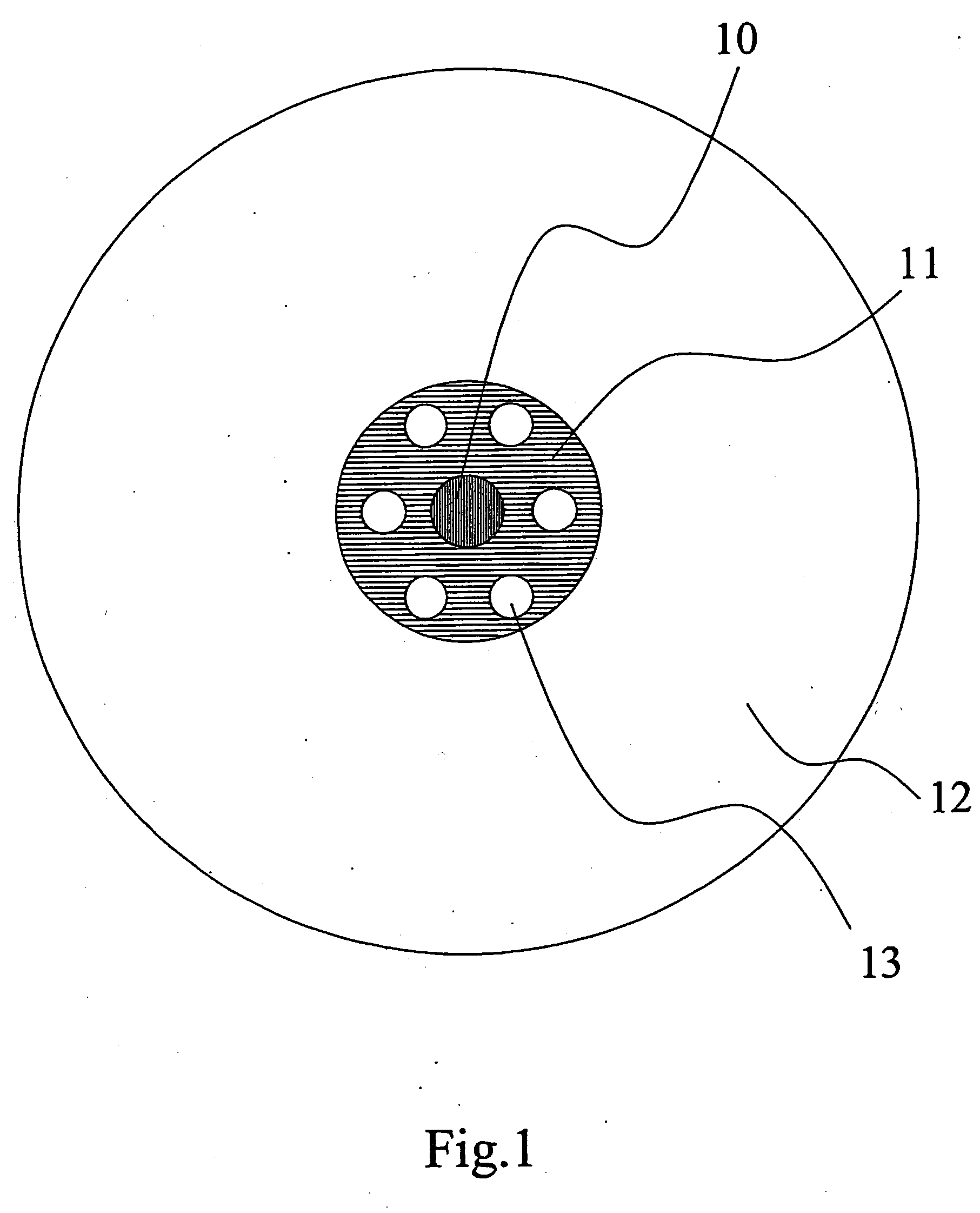
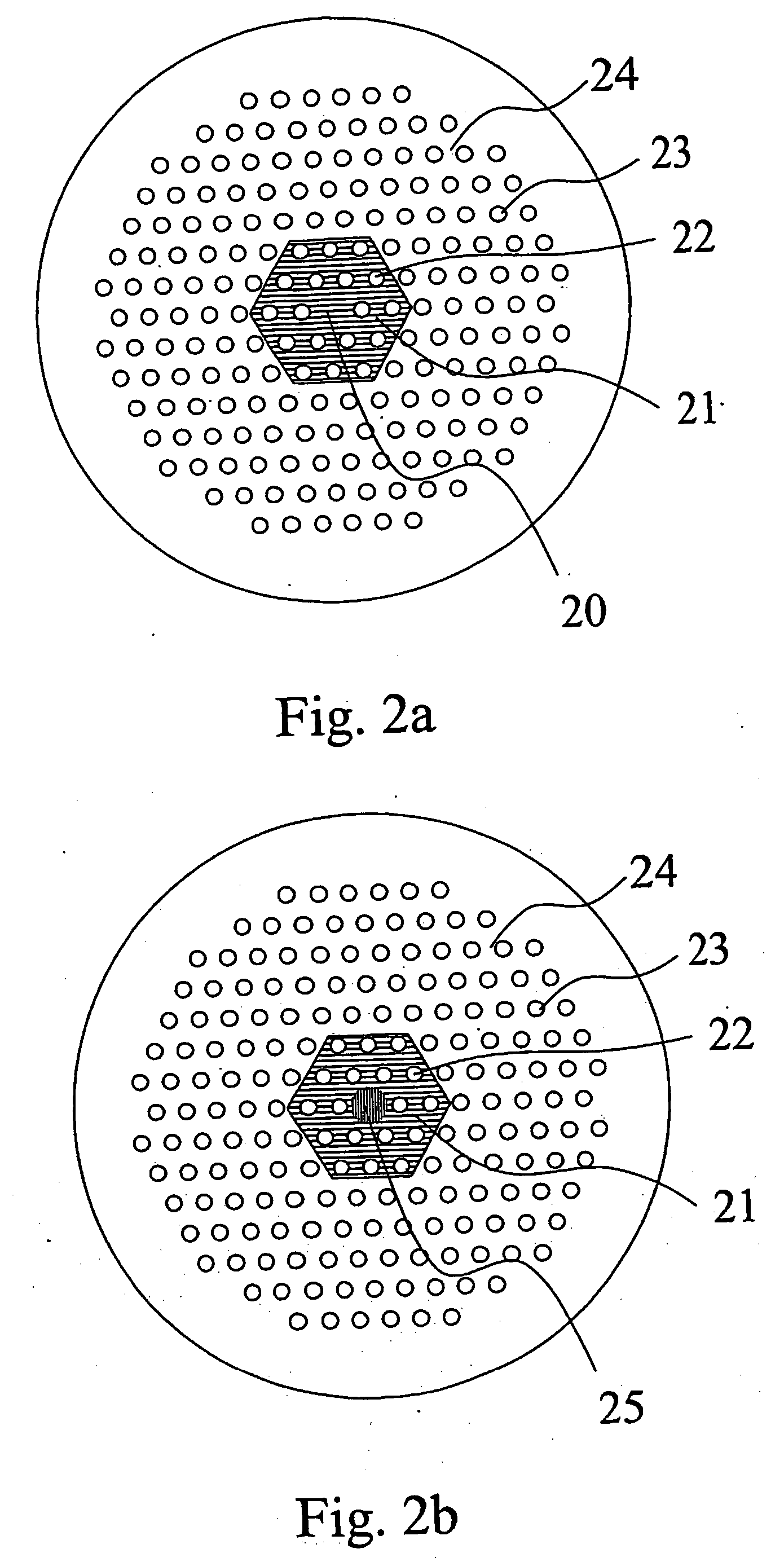
[0116] According to one aspect of the present invention, these objects are fulfilled by providing an optical fibre having an axial direction and a cross section perpendicular to said axial direction, said optical fibre comprising a core region, an inner cladding region and an outer cladding region, wherein said inner cladding region comprises inner cladding features and an inner background material of refractive index n1, and said outer cladding region comprises an outer background material of refractive index n2, and n1 is larger than n2.

[0117] In a preferred embodiment, said core region comprises material with a refractive index ncore, and ncore is equal to n1. This provides for example to use similar background material for the inner cladding region and the core region.

[0118] In a preferred embodiment, said core region comprises material with a refractive index ncore, and ncore is larger than n1. This allows for example to design an optical fibre with a high nonlinear coefficie...


PUM

PropertyMeasurementUnit
Fractionaaaaaaaaaa
Fractionaaaaaaaaaa
Diameteraaaaaaaaaa

Abstract

A method of coupling a spliceable optical fibre for transmission of light in its longitudinal direction to an optical component, the method comprising (A) providing the spliceable optical fibre, said spliceable optical fibre comprising: (a) a core region (10, 20, 25, 30, 110); and (b) a microstructured cladding region, said cladding region surrounding said core region and comprising: (b1) an inner cladding region with inner cladding features (13, 22, 112) arranged in an inner cladding background material (11, 21, 111) with a refractive index n1, said inner cladding features comprising thermally collapsible holes or voids, and (b2) an outer cladding region with an outer cladding background material (12, 24, 114) with a refractive index n2; said spliceable optical fibre having at least one end; (B) collapsing said thermally collapsible holes or voids by heating said least one end of said spliceable optical fibre; and (C) coupling said collapsed spliceable optical fibre end to the optical component. A spliceable optical fibre; a preform for producing a spliceable optical fibre; a method of producing a spliceable optical fibre comprising drawing of the preform; a heat-treated spliceable optical fibre; an article comprising a spliceable optical fibre is further disclosed.

Description

BACKGROUND OF THE INVENTION [0001] The present invention relates to a method of coupling a spliceable optical fibre to an optical component; a spliceable optical fibre; a preform for producing a spliceable optical fibre; a method of producing a spliceable optical fibre comprising drawing of the preform; a heat-treated spliceable optical fibre; an article comprising a spliceable optical fibre. THE TECHNICAL FIELD [0002] In recent years a new class of optical fibres has appeared. The optical guiding mechanism in these fibres is provided by introducing a number of holes or voids in the optical fibres. These holes typically run parallel with the fibre and extend along the fibre length. Such fibres are generally described by A. Bjarklev et al. in “Photonic Crystal Fibres”, Kluwer Academic Publishers, 2003 (ISBN 1-4020-7610-X), which is referred to in the following as [Bjarklev et al.]). [0003] The light guiding principle can either be based on Total Internal Reflection (TIR) similar to t...

Claims


Application Information

Patent Timeline
IPC IPC(8): G02B6/255G02B6/02
CPCG02B6/02328G02B6/02333G02B6/02347Y10T29/49826G02B6/02376G02B6/02385G02B6/255G02B6/02357
Inventor BROENG, JESBRISTIANSEN, RENE ENGEL
Owner CRYSTAL FIBRE AS
Why Eureka
Try Eureka